Каталог Sumitomo инструмент для обработки канавок - страница 7
Навигация
 Каталог Sumitomo пластины с алмазными вставками Sumidia
 Каталог Sumitomo микроинструмент
 Общий каталог Sumitomo 2012
 Каталог Sumitomo пластины с режущей кромкой-моноалмаз Sumicristal
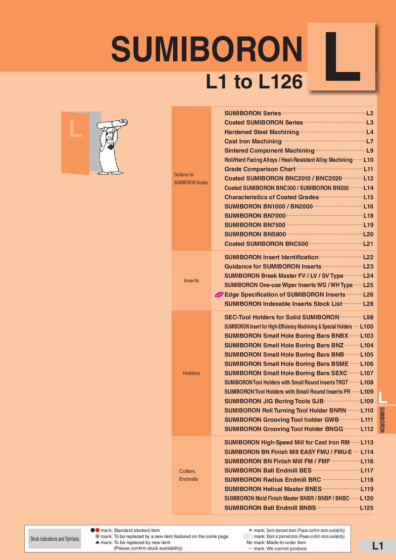 Каталог Sumitomo пластины с кубическим нитридом бора Sumiboron
 Общий каталог Sumitomo 2018 - 2019
- F001
- F002
- F003
- F004
- F005
- F006
- F007
- F008
- F009
- F010
- F011
- F012
- F013
- F014
- F015
- F016
- F017
- F018
- F019
- F020
- F021
- F022
- F023
- F024
- F025
- F026
- F027
- F028
- F029
- F030
- F031
- F032
- F033
- F034
- F035
- F036
- F037
- F038
- F039
- F040
- F041
- F042
- F043
- F044
- F045
- F046
- F047
- F048
- F049
- F050
- F051
- F052
- F053
- F054
- F055
- F056
- F057
- F058
- F059
- F060
- F061
- F062
- F063
- F064
- F065
- F066
- F067
- F068
- F069
- F070
- F071
- F072
- F073
- F074
- F075
- F076
- F077
- F078
- F079
- F080
- F081
- F082
- F083
- F084
- F085
- F086
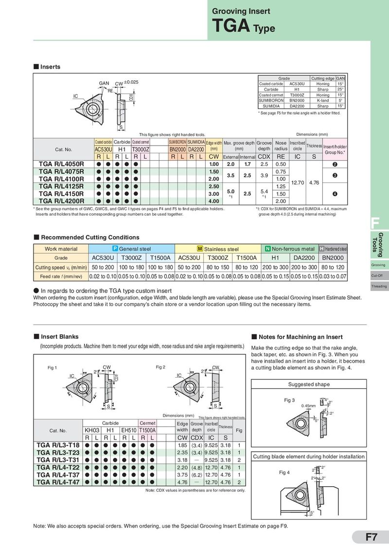
Grooving Insert TGA Type ■ Inserts 0.025 Grade Cutting edge GAN GAN CW Coated carbide AC530U Honing 15° RE Carbide H1 Sharp 25° IC CDX Coated cermet T3000Z Honing 15° SUMIBORON BN2000 K-land 5° SUMIDIA DA2200 Sharp 15° * See page F5 for the rake angle with a holder fitted. S This figure shows right handed tools. Dimensions (mm) Coated carbide Carbide Coated cermet SUMIBORON SUMIDIA Edge width Max. groove depth Groove Nose Inscribed Thickness Cat. No. AC530U H1 T3000Z BN2000 DA2200 (mm) (mm) depth radius circle Insert/holder R L R L R L R L R L CW CDX RE IC S Group No.* External Internal TGA R/L4050R D D D D D 1.00 2.0 1.7 2.5 0.50 ❷ TGA R/L4075R D D D D D 1.50 3.5 2.5 3.9 0.75 ❸ TGA R/L4100R D D D D D 2.00 1.00 12.70 4.76 TGA R/L4125R D D D D D 2.50 1.25 TGA R/L4150R D D D D D 3.00 5.0 2.5 5.4 1.50 ❹ TGA R/L4200R *1 *1 D D D D D 4.00 2.00 * See the group numbers of GWC, GWCS, and GWC I types on pages F4 and F5 to find applicable holders. *1: CDX for SUMIBORON and SUMIDIA = 4.4, maximum Inserts and holders that have corresponding group numbers can be used together. groove depth 4.0 (2.5 during internal machining) F ■ Recommended Cutting Conditions Tools Grooving Work material P General steel M Stainless steel N Non-ferrous metal H Hardened steel Grade AC530U T3000Z T1500A AC530U T3000Z T1500A H1 DA2200 BN2000 Cutting speed vc (m/min) 50 to 200 100 to 180 100 to 180 50 to 200 80 to 150 80 to 120 200 to 300 200 to 300 80 to 120 Grooving Feed rate f (mm/rev) 0.02 to 0.10 0.05 to 0.10 0.05 to 0.08 0.02 to 0.10 0.05 to 0.08 0.05 to 0.08 0.05 to 0.15 0.05 to 0.15 0.03 to 0.07 Cut-Off Threading ● In regards to ordering the TGA type custom insert When ordering the custom insert (configuration, edge Width, and blade length are variable), please use the Special Grooving Insert Estimate Sheet. Photocopy the sheet and take it to our company's chain store or a vendor location upon filling out the necessary items. ■ Insert Blanks ■ Notes for Machining an Insert (Incomplete products. Machine them to meet your edge width, nose radius and rake angle requirements.) Make the cutting edge so that the rake angle, back taper, etc. as shown in Fig. 3. When you have installed an insert into a holder, it becomes Fig 1 CW Fig 2 CW a cutting blade element as shown in Fig. 4. 2° IC 2° IC CDX Suggested shape Fig 3 4° 2° S S 0.45mm 4° 2° Dimensions (mm) This figure shows right handed tools. Carbide Cermet Edge Groove Inscribed 5° Cat. No. KH03 H1 EH510 T1500A width depth circle Thickness Fig R L R L R L R L CW CDX IC S TGA R/L3-T18 D D D D D D D D 1.85 (3.4) 9.525 3.18 1 TGA R/L3-T23 D D D D D D D D 2.35 (3.4) 9.525 3.18 1 Cutting blade element during holder installation TGA R/L3-T31 D D D D D D D D 3.18 Q 9.525 3.18 2 TGA R/L4-T22 D D D D D D D D 2.20 (4.8) 12.70 4.76 1 2° 2° TGA R/L4-T37 D D D D D D D D 3.75 (6.2) 12.70 4.76 1 Fig 4 TGA R/L4-T47 2° 2° D D D D D D D D 4.76 Q 12.70 4.76 2 Note: CDX values in parentheses are for reference only. 5° Note: We also accepts special orders. When ordering, use the Special Grooving Insert Estimate on page F9. F7