Каталог Sumitomo инструмент для обработки канавок - страница 20
Навигация
 Каталог Sumitomo пластины с алмазными вставками Sumidia
 Каталог Sumitomo микроинструмент
 Общий каталог Sumitomo 2012
 Каталог Sumitomo пластины с режущей кромкой-моноалмаз Sumicristal
 Каталог Sumitomo пластины с кубическим нитридом бора Sumiboron
 Общий каталог Sumitomo 2018 - 2019
- F001
- F002
- F003
- F004
- F005
- F006
- F007
- F008
- F009
- F010
- F011
- F012
- F013
- F014
- F015
- F016
- F017
- F018
- F019
- F020
- F021
- F022
- F023
- F024
- F025
- F026
- F027
- F028
- F029
- F030
- F031
- F032
- F033
- F034
- F035
- F036
- F037
- F038
- F039
- F040
- F041
- F042
- F043
- F044
- F045
- F046
- F047
- F048
- F049
- F050
- F051
- F052
- F053
- F054
- F055
- F056
- F057
- F058
- F059
- F060
- F061
- F062
- F063
- F064
- F065
- F066
- F067
- F068
- F069
- F070
- F071
- F072
- F073
- F074
- F075
- F076
- F077
- F078
- F079
- F080
- F081
- F082
- F083
- F084
- F085
- F086
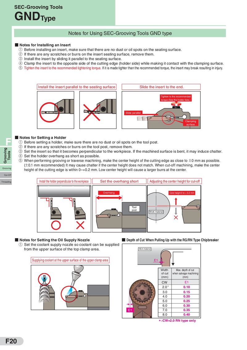
SEC-Grooving Tools GNDType Notes for Using SEC-Grooving Tools GND type ■ Notes for Installing an Insert ① Before installing an insert, make sure that there are no dust or oil spots on the seating surface. ② If there are any scratches or burrs on the insert seating surface, remove them. ③ Install the insert by sliding it parallel to the seating surface. ④ Clamp the insert to the opposite side of the cutting edge (holder side) while making it contact with the clamping surface. ⑤ Tighten the insert to the recommended tightening torque. If it is made tighter than the recommended torque, the insert may break resulting in injury. Install the insert parallel to the seating surface Slide the insert to the end. Tighten to the recommended torque (See the holder lists.) Slide parallel Clamping surface F ■ Notes for Setting a Holder ① Before setting a holder, make sure there are no dust or oil spots on the tool post. Grooving ② If there are any scratches or burrs on the tool post, remove them. Tools ③ Set the insert so that it becomes perpendicular to the workpiece. If the machined surface is bent, it may induce chatter. ④ Set the holder overhang as short as possible. ⑤ When performing grooving or traverse machining, make the center height of the cutting edge as close to ±0 mm as possible. (±0.1 mm recommended) It may cause chatter if the center height does not match. When cut-off machining, make the center Grooving height of the cutting edge is within 0–+0.2 mm. Low center height will cause a larger burrs at the center. Cut-Off Threading Install the holder perpendicular to the workpiece Set the overhang short Adjusting the center height for cut-off Overhang Core height 0 to + 0.2 mm Tool post Work material ■ Notes for Setting the Oil Supply Nozzle ■ Depth of Cut When Pulling Up with the RG/RN Type Chipbreaker ① Set the coolant supply nozzle so coolant can be supplied from the upper surface of the top clamp area. Work material Supplying coolant at the upper surface of the upper clamp area E1 Width Max. depth of cut of cut when salvage machining (mm) (mm) CW E1 2.0* 0.10 3.0 0.15 4.0 0.20 5.0 0.25 6.0 0.30 E1 7.0 0.35 8.0 0.40 㸨:CW=2.0 RN type only F20