Каталог Sumitomo инструмент для обработки канавок - страница 37
Навигация
 Каталог Sumitomo пластины с алмазными вставками Sumidia
 Каталог Sumitomo микроинструмент
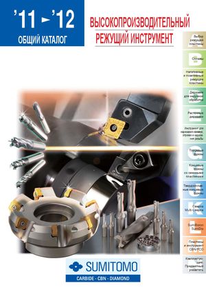 Общий каталог Sumitomo 2012
 Каталог Sumitomo пластины с режущей кромкой-моноалмаз Sumicristal
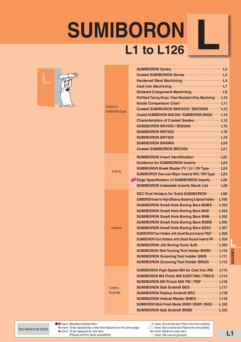 Каталог Sumitomo пластины с кубическим нитридом бора Sumiboron
 Общий каталог Sumitomo 2018 - 2019
- F001
- F002
- F003
- F004
- F005
- F006
- F007
- F008
- F009
- F010
- F011
- F012
- F013
- F014
- F015
- F016
- F017
- F018
- F019
- F020
- F021
- F022
- F023
- F024
- F025
- F026
- F027
- F028
- F029
- F030
- F031
- F032
- F033
- F034
- F035
- F036
- F037
- F038
- F039
- F040
- F041
- F042
- F043
- F044
- F045
- F046
- F047
- F048
- F049
- F050
- F051
- F052
- F053
- F054
- F055
- F056
- F057
- F058
- F059
- F060
- F061
- F062
- F063
- F064
- F065
- F066
- F067
- F068
- F069
- F070
- F071
- F072
- F073
- F074
- F075
- F076
- F077
- F078
- F079
- F080
- F081
- F082
- F083
- F084
- F085
- F086
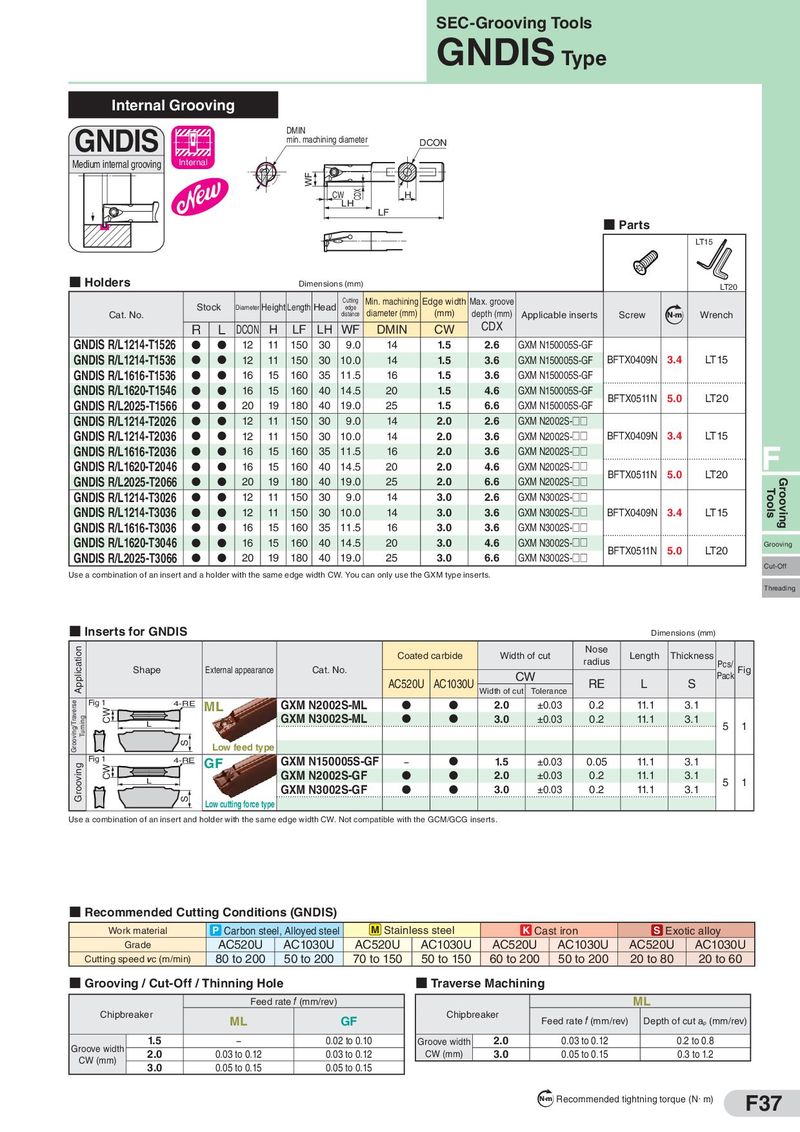
SEC-Grooving Tools GNDIS Type Internal Grooving GNDIS DMIN min. machining diameter DCON Medium internal grooving Internal WF CW CDX H LH LF ■ Parts LT15 ■ Holders Dimensions (mm) LT20 Stock Diameter Height Length Head Cutting Min. machining Edge width Max. groove edge diameter (mm) (mm) depth (mm) Cat. No. distance Applicable inserts Screw Nm Wrench R L DCON H LF LH WF DMIN CW CDX GNDIS R/L1214-T1526 D D 12 11 150 30 9.0 14 1.5 2.6 GXM N150005S-GF GNDIS R/L1214-T1536 D D 12 11 150 30 10.0 14 1.5 3.6 GXM N150005S-GF BFTX0409N 3.4 LT15 GNDIS R/L1616-T1536 D D 16 15 160 35 11.5 16 1.5 3.6 GXM N150005S-GF GNDIS R/L1620-T1546 D D 16 15 160 40 14.5 20 1.5 4.6 GXM N150005S-GF BFTX0511N 5.0 LT20 GNDIS R/L2025-T1566 D D 20 19 180 40 19.0 25 1.5 6.6 GXM N150005S-GF GNDIS R/L1214-T2026 D D 12 11 150 30 9.0 14 2.0 2.6 GXM N2002S-□□ GNDIS R/L1214-T2036 D D 12 11 150 30 10.0 14 2.0 3.6 GXM N2002S-□□ BFTX0409N 3.4 LT15 GNDIS R/L1616-T2036 D D 16 15 160 35 11.5 16 2.0 3.6 GXM N2002S-□□ F GNDIS R/L1620-T2046 D D 16 15 160 40 14.5 20 2.0 4.6 GXM N2002S-□□ BFTX0511N 5.0 LT20 GNDIS R/L2025-T2066 D D 20 19 180 40 19.0 25 2.0 6.6 GXM N2002S-□□ Grooving GNDIS R/L1214-T3026 D D 12 11 150 30 9.0 14 3.0 2.6 GXM N3002S-□□ Tools GNDIS R/L1214-T3036 D D 12 11 150 30 10.0 14 3.0 3.6 GXM N3002S-□□ BFTX0409N 3.4 LT15 GNDIS R/L1616-T3036 D D 16 15 160 35 11.5 16 3.0 3.6 GXM N3002S-□□ GNDIS R/L1620-T3046 D D 16 15 160 40 14.5 20 3.0 4.6 GXM N3002S-□□ BFTX0511N 5.0 LT20 Grooving GNDIS R/L2025-T3066 D D 20 19 180 40 19.0 25 3.0 6.6 GXM N3002S-□□ Cut-Off Use a combination of an insert and a holder with the same edge width CW. You can only use the GXM type inserts. Threading ■ Inserts for GNDIS Dimensions (mm) Application Coated carbide Width of cut Nose Length Thickness Shape External appearance Cat. No. radius Pcs/ Fig AC520U AC1030U CW RE L S Pack Width of cut Tolerance Grooving/Traverse Fig 1 4-RE ML GXM N2002S-ML D D 2.0 ±0.03 0.2 11.1 3.1 Turning CW L GXM N3002S-ML D D 3.0 ±0.03 0.2 11.1 3.1 5 1 S Low feed type Grooving Fig 1 4-RE GF GXM N150005S-GF − D 1.5 ±0.03 0.05 11.1 3.1 CW L GXM N2002S-GF D D 2.0 ±0.03 0.2 11.1 3.1 5 1 GXM N3002S-GF D D 3.0 ±0.03 0.2 11.1 3.1 S Low cutting force type Use a combination of an insert and holder with the same edge width CW. Not compatible with the GCM/GCG inserts. ■ Recommended Cutting Conditions (GNDIS) Work material P Carbon steel, Alloyed steel M Stainless steel K Cast iron S Exotic alloy Grade AC520U AC1030U AC520U AC1030U AC520U AC1030U AC520U AC1030U Cutting speed vc (m/min) 80 to 200 50 to 200 70 to 150 50 to 150 60 to 200 50 to 200 20 to 80 20 to 60 ■ Grooving / Cut-Off / Thinning Hole ■ Traverse Machining Feed rate f (mm/rev) ML Chipbreaker ML GF Chipbreaker Feed rate f (mm/rev) Depth of cut ap (mm/rev) Groove width 1.5 − 0.02 to 0.10 Groove width 2.0 0.03 to 0.12 0.2 to 0.8 CW (mm) 2.0 0.03 to 0.12 0.03 to 0.12 CW (mm) 3.0 0.05 to 0.15 0.3 to 1.2 3.0 0.05 to 0.15 0.05 to 0.15 N m Recommended tightning torque (N・m) F37