Каталог Sumitomo инструмент для обработки канавок - страница 3
Навигация
 Каталог Sumitomo пластины с алмазными вставками Sumidia
 Каталог Sumitomo микроинструмент
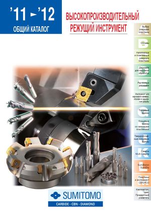 Общий каталог Sumitomo 2012
 Каталог Sumitomo пластины с режущей кромкой-моноалмаз Sumicristal
 Каталог Sumitomo пластины с кубическим нитридом бора Sumiboron
 Общий каталог Sumitomo 2018 - 2019
- F001
- F002
- F003
- F004
- F005
- F006
- F007
- F008
- F009
- F010
- F011
- F012
- F013
- F014
- F015
- F016
- F017
- F018
- F019
- F020
- F021
- F022
- F023
- F024
- F025
- F026
- F027
- F028
- F029
- F030
- F031
- F032
- F033
- F034
- F035
- F036
- F037
- F038
- F039
- F040
- F041
- F042
- F043
- F044
- F045
- F046
- F047
- F048
- F049
- F050
- F051
- F052
- F053
- F054
- F055
- F056
- F057
- F058
- F059
- F060
- F061
- F062
- F063
- F064
- F065
- F066
- F067
- F068
- F069
- F070
- F071
- F072
- F073
- F074
- F075
- F076
- F077
- F078
- F079
- F080
- F081
- F082
- F083
- F084
- F085
- F086
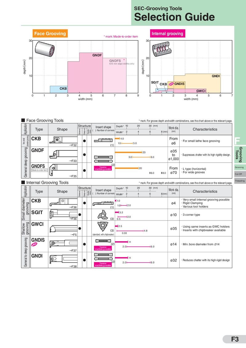
SEC-Grooving Tools Selection Guide Face Grooving * mark: Made-to-order item Internal grooving 30 30 GNDF depth(mm) 20 GNDFS * depth(mm) 20 6/8 mm edge widths only 10 10 GNDI SGIT CKB GNDIS CKB GWCI 0 1 2 3 4 5 6 7 8 9 0 1 2 3 4 5 6 7 width (mm) width (mm) ■ Face Grooving Tools * mark: For groove depth and width combinations, see the chart above or the relevant page. Application Structure Insert shape Depth* 10 20 30 (mm) Work dia. Type Shape Screw-on Clamp-on Double clamp ( ): Number of corners 2 4 6 8 (mm) (mm) Characteristics Width* Very small diameter grooving CKB 4.0 From ・For small lathe face grooving F →F32 (1) 1.5 3.0 ø6 grooving GNDF 23 ø35 Tools Grooving 3.0 6.0 to ・Suppresses chatter with its high rigidity design. deep →F33 ø1,000 GNDFS Traverse (2) General machining possible 20 From ・L type (horizontal) Grooving Made-to-order item ø70 ・For wide grooves 6.0 8.0 Cut-Off →F35 ■ Internal Grooving Tools * mark: For groove depth and width combinations, see the chart above or the relevant page. Threading Application Structure Insert shape Depth* 10 20 30 (mm) Work dia. Type Shape Screw-on Clamp-on Double clamp ( ): Number of corners 2 4 6 8(mm) (mm) Characteristics Width* Small diameter CKB 1.0 ・Very small internal grooving possible grooving 1.0 2.0 ø4 ・Rigid Clamping →F36 (1) ・Various tool holders SGIT 3.2 ø10 ・3 corner type →F36 (3) 2.0 0.5 Shallow grooving GWCI 2.5 ・Using same inserts as GWC holders (3) 4.8 ø35 ・Inserts with chipbreaker available →F5 (standard, with chipbreaker) 0.33 General to deep grooving GNDIS 11 (2) ø14 ・Min. bore diameter from φ14 Traverse 2.0 6.0 →F37 machining possible GNDI 11 (2) 2.0 6.0 ø32 ・Reduces chatter with its high rigid design Traverse →F38 machining possible F3