Каталог Sumitomo инструмент для обработки канавок - страница 18
Навигация
 Каталог Sumitomo пластины с алмазными вставками Sumidia
 Каталог Sumitomo микроинструмент
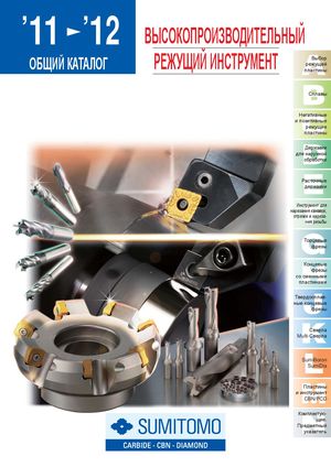 Общий каталог Sumitomo 2012
 Каталог Sumitomo пластины с режущей кромкой-моноалмаз Sumicristal
 Каталог Sumitomo пластины с кубическим нитридом бора Sumiboron
 Общий каталог Sumitomo 2018 - 2019
- F001
- F002
- F003
- F004
- F005
- F006
- F007
- F008
- F009
- F010
- F011
- F012
- F013
- F014
- F015
- F016
- F017
- F018
- F019
- F020
- F021
- F022
- F023
- F024
- F025
- F026
- F027
- F028
- F029
- F030
- F031
- F032
- F033
- F034
- F035
- F036
- F037
- F038
- F039
- F040
- F041
- F042
- F043
- F044
- F045
- F046
- F047
- F048
- F049
- F050
- F051
- F052
- F053
- F054
- F055
- F056
- F057
- F058
- F059
- F060
- F061
- F062
- F063
- F064
- F065
- F066
- F067
- F068
- F069
- F070
- F071
- F072
- F073
- F074
- F075
- F076
- F077
- F078
- F079
- F080
- F081
- F082
- F083
- F084
- F085
- F086
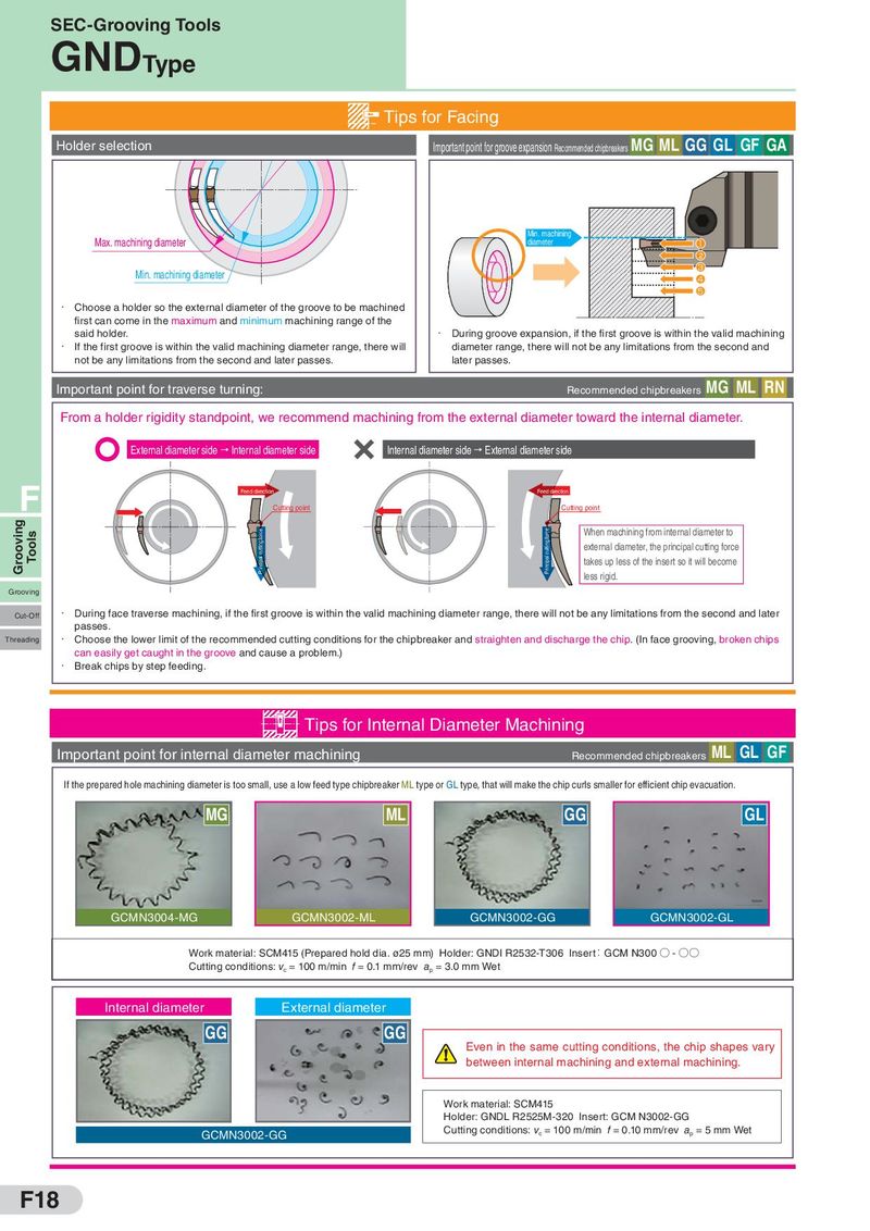
SEC-Grooving Tools GNDType Tips for Facing Holder selection Important point for groove expansion Recommended chipbreakers MG ML GG GL GF GA Max. machining diameter Min. machining diameter 1 2 Min. machining diameter 3 4 5 ・ Choose a holder so the external diameter of the groove to be machined first can come in the maximum and minimum machining range of the said holder. ・ During groove expansion, if the first groove is within the valid machining ・ If the first groove is within the valid machining diameter range, there will diameter range, there will not be any limitations from the second and not be any limitations from the second and later passes. later passes. Important point for traverse turning: MG Recommended chipbreakers ML RN From a holder rigidity standpoint, we recommend machining from the external diameter toward the internal diameter. External diameter side → Internal diameter side Internal diameter side → External diameter side F Feed direction Feed direction Cutting point Cutting point Grooving Tools Principal cutting force Principal cutting force When machining from internal diameter to external diameter, the principal cutting force takes up less of the insert so it will become less rigid. Grooving Cut-Off ・ During face traverse machining, if the first groove is within the valid machining diameter range, there will not be any limitations from the second and later passes. Threading ・ Choose the lower limit of the recommended cutting conditions for the chipbreaker and straighten and discharge the chip. (In face grooving, broken chips can easily get caught in the groove and cause a problem.) ・ Break chips by step feeding. Tips for Internal Diameter Machining Important point for internal diameter machining ML Recommended chipbreakers GL GF If the prepared hole machining diameter is too small, use a low feed type chipbreaker ML type or GL type, that will make the chip curls smaller for efficient chip evacuation. MG ML GG GL GCMN3004-MG GCMN3002-ML GCMN3002-GG GCMN3002-GL Work material: SCM415 (Prepared hold dia. ø25 mm) Holder: GNDI R2532-T306 Insert:GCM N300 ○ - ○○ Cutting conditions: vc = 100 m/min f = 0.1 mm/rev ap = 3.0 mm Wet Internal diameter External diameter GG GG Even in the same cutting conditions, the chip shapes vary between internal machining and external machining. Work material: SCM415 Holder: GNDL R2525M-320 Insert: GCM N3002-GG GCMN3002-GG Cutting conditions: vc = 100 m/min f = 0.10 mm/rev ap = 5 mm Wet F18