Каталог Sumitomo инструмент для обработки канавок - страница 41
Навигация
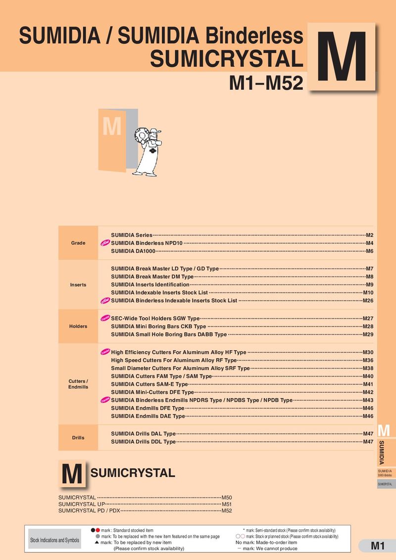 Каталог Sumitomo пластины с алмазными вставками Sumidia
 Каталог Sumitomo микроинструмент
 Общий каталог Sumitomo 2012
 Каталог Sumitomo пластины с режущей кромкой-моноалмаз Sumicristal
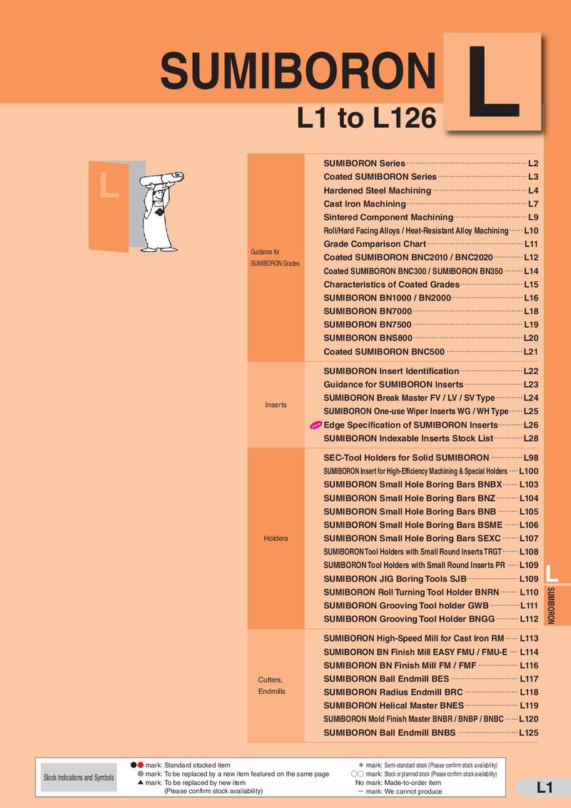 Каталог Sumitomo пластины с кубическим нитридом бора Sumiboron
 Общий каталог Sumitomo 2018 - 2019
- F001
- F002
- F003
- F004
- F005
- F006
- F007
- F008
- F009
- F010
- F011
- F012
- F013
- F014
- F015
- F016
- F017
- F018
- F019
- F020
- F021
- F022
- F023
- F024
- F025
- F026
- F027
- F028
- F029
- F030
- F031
- F032
- F033
- F034
- F035
- F036
- F037
- F038
- F039
- F040
- F041
- F042
- F043
- F044
- F045
- F046
- F047
- F048
- F049
- F050
- F051
- F052
- F053
- F054
- F055
- F056
- F057
- F058
- F059
- F060
- F061
- F062
- F063
- F064
- F065
- F066
- F067
- F068
- F069
- F070
- F071
- F072
- F073
- F074
- F075
- F076
- F077
- F078
- F079
- F080
- F081
- F082
- F083
- F084
- F085
- F086
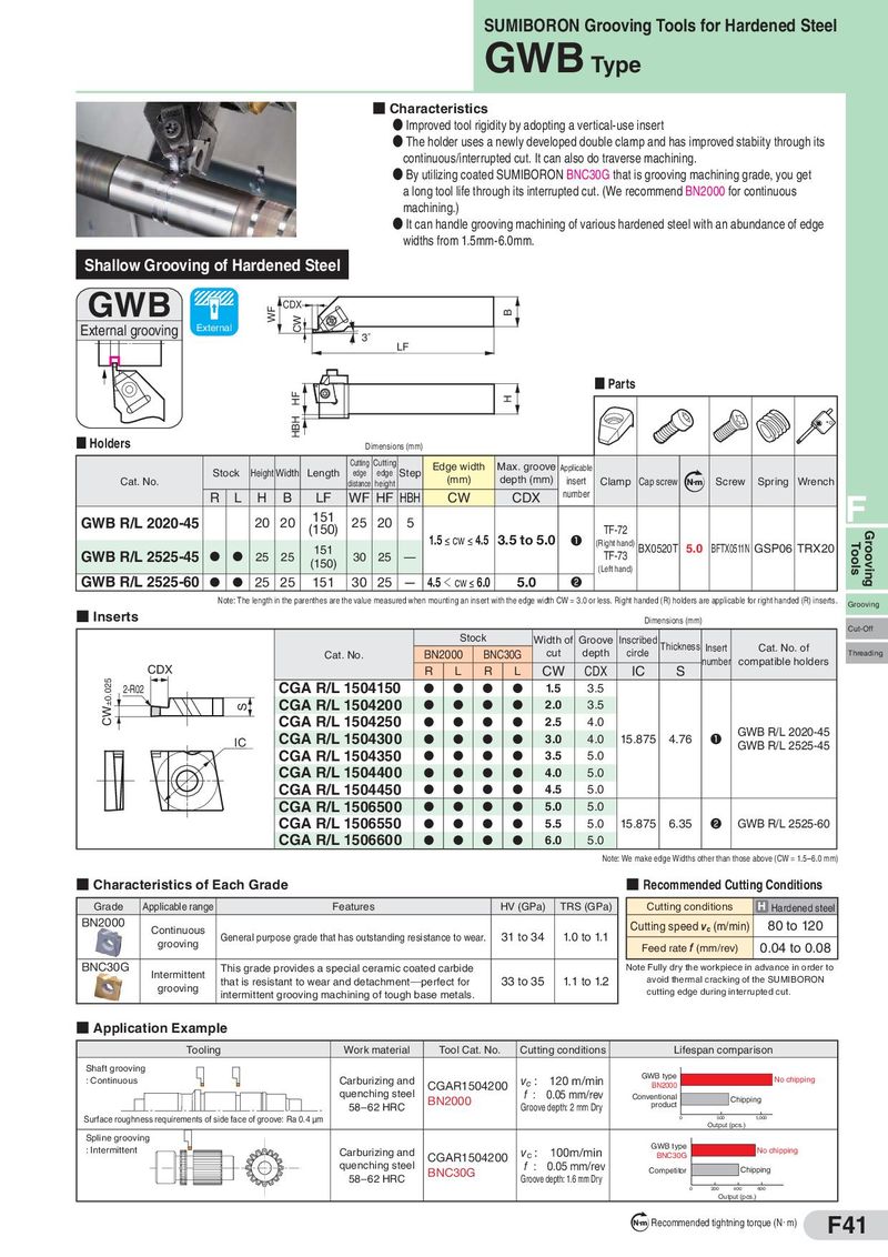
Shallow Grooving of Hardened Steel
GWB
CDX External grooving External
SUMIBORON Grooving Tools for Hardened Steel
GWB
- Characteristics
- Improved tool rigidity by adopting a vertical-use insert
- The holder uses a newly developed double clamp and has improved stabiity through its continuous/interrupted cut. It can also do traverse machining.
- By utilizing coated SUMIBORON BNC30G that is grooving machining grade, you get a long tool life through its interrupted cut. (We recommend BN2000 for continuous machining.)
- It can handle grooving machining of various hardened steel with an abundance of edge widths from 1.5mm-6.0mm.
3˚ LF
- Parts
- Holders
Dimensions (mm)
Cutting Cutting Edge width Max. groove
| Stock | Height Width Length | Step | Applicable | ||
| edge | edge |
Cat. No. distance height (mm) depth (mm) insert Clamp Cap screw N m Screw Spring Wrench
| R | L | H | B | LF | WF HF HBH | CW | CDX | number | F | ||||
| GWB R/L 2020-45 | 151 | ||||||||||||
| 20 20 | 25 20 | 5 | |||||||||||
| (150) | TF-72 | ||||||||||||
| 1.5 ≤ cw ≤ 4.5 3.5 to 5.0 | ❶ |
(Right hand) BX0520T 5.0 BFTX0511N GSP06 TRX20
GWB R/L 2525-45 D D 151
| 25 | 25 | 30 | 25 | — | TF-73 | |
| (150) | ||||||
| (Left hand) |
GWB R/L 2525-60 D D 25 25 151 30 25 — 4.5 < cw ≤ 6.0 5.0 ❷
Note: The length in the parenthes are the value measured when mounting an insert with the edge width CW = 3.0 or less. Right handed (R) holders are applicable for right handed (R) inserts.
- Grooving
Inserts Dimensions (mm) Cut-Off Stock Width of Groove Inscribed Thickness Insert Cat. No. of
| Cat. No. BN2000 | BNC30G | cut | depth | circle | Threading | |||||
| number | compatible holders | |||||||||
| CDX | R | L | R | L | CW | CDX | IC | S | ||
| 2-R02 CGA R/L 1504150 | D | D | D | D | 1.5 | 3.5 | ||||
| CGA R/L 1504200 | D | D | D | D | 2.0 | 3.5 | ||||
| CGA R/L 1504250 | D | D | D | D | 2.5 | 4.0 | ||||
| CGA R/L 1504300 | D | D | D | D | ❶ | GWB R/L 2020-45 | ||||
| IC | 3.0 | 4.0 | 15.875 | 4.76 | ||||||
| GWB R/L 2525-45 | ||||||||||
| CGA R/L 1504350 | D | D | D | D | 3.5 | 5.0 | ||||
| CGA R/L 1504400 | D | D | D | D | 4.0 | 5.0 | ||||
| CGA R/L 1504450 | D | D | D | D | 4.5 | 5.0 | ||||
| CGA R/L 1506500 | D | D | D | D | 5.0 | 5.0 | ||||
| CGA R/L 1506550 | D | D | D | D | 5.5 | 5.0 | 15.875 | 6.35 | ❷ | GWB R/L 2525-60 |
| CGA R/L 1506600 | D | D | D | D | 6.0 | 5.0 |
Note: We make edge Widths other than those above (CW = 1.5–6.0 mm)
- Characteristics of Each Grade
- Recommended Cutting Conditions
| Grade | Applicable range | Features | HV(GPa) | TRS(GPa) | Cuttingconditions | H Hardened steel |
| BN2000 | Continuous | Gl dhhdii | 31 t 34 | 10 t 11 | Cutting speedvc(m/min) | 80 to 120 |
| grooving | enera purpose grae tat as outstanng resstance to wear. | o | . o . | Feed ratef(mm/rev) | 0.04 to 0.08 | |
| BNC30G | Intermittent grooving | This grade provides a special ceramic coated carbide that is resistant to wear and detachment perfect for intermittent grooving machining of tough base metals. | 33 to 35 | 1.1 to 1.2 | Note Fully dry the workpiece in avoid thermal cracking of cutting edge during interr | advance in order to the SUMIBORON upted cut. |
- Application Example
| Tooling Work material | Tool Cat. No. | Cutting conditions | Lifespan comparison | ||
| Shaft grooving | |||||
| : Continuous | Carburizing and | v | : 120 m/min | GWB type | |
| CGAR1504200 | c | No chipping | |||
| BN2000 | |||||
| quenching steel | f : 0.05 mm/rev | ||||
| BN2000 | Chipping Conventional | ||||
| 58–62 HRC | Groove depth: 2 mm Dry | product | |||
| Surface roughness requirements of side face of groove: Ra 0.4 μm | 1,000 500 0 | ||||
| Output (pcs.) | |||||
| Spline grooving | |||||
| : Intermittent | GWB type | ||||
| Carburizing and | v | : 100m/min | No chipping | ||
| CGAR1504200 | c | BNC30G | |||
| quenching steel | f : 0.05 mm/rev | ||||
| BNC30G | Chipping Competitor |
58–62 HRC Groove depth: 1.6 mm Dry Output (pcs.)