Общий каталог ZCC-CT 2019 - страница 1113
Навигация
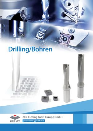 Каталог ZCC-CT сверла со сменными пластинами
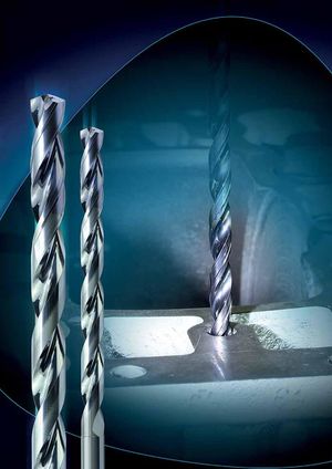 Каталог ZCC-CT сверла монолитные
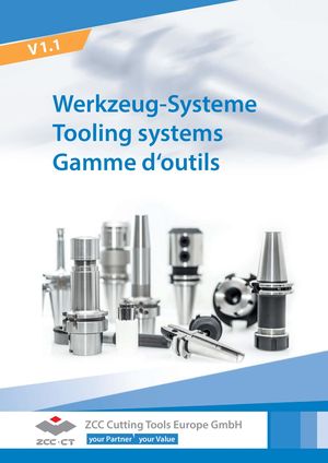 Каталог ZCC-CT оснастка
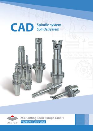 Каталог ZCC-CT расточные системы
 Каталог ZCC-CT фрезы со сменными пластинами
 Каталог ZCC-CT фрезы монолитные
- Title page
- Summary
- Turning
- Overview
- Insert overview negative inserts
- Insert overview positive inserts
- ISO code – general turning inserts
- ISO code – PCBN & PCD inserts
- Insert overview CBN & PKD
- Insert overview Ceramic
- Overview holder external
- Overview boring bars
- Explanation chipbreaker -ADF -AHF
- Explanation chipbreaker-ZM
- Explanation chipbreaker -NGF -SNR
- Grade explanation YBG101
- Grade explanation YB9320
- Grade explanationYB7315
- Simply Coloured
- Chip breaker overview negativ inserts
- Application fields of chip breakers
- Finishing
- Wiper
- Medium machining
- Roughing
- Chip breaker overview positiv inserts
- Application fields of chip breakers
- Fine-finishing
- Finishing
- Medium machining
- Roughing
- Aluminium machining
- Grade overview CVD
- Application field of grades CVD
- Grade overview PVD
- Application field of grades PVD
- Grade explanation Ceramic
- Grade explanation uncoated cermented cabidel
- Grade explanation CBN
- Grade explanation PKD
- Grade explanation Cermet
- Application felds of grade
- Conversion table metric/imperial
- Negative inserts
- CN**
- DN**
- SN**
- TN**
- VN**
- WN**
- RN**
- KN**
- Railway wheel machining
- Positiv inserts
- CC**
- CP**
- DC**
- DP**
- RC**
- SC**
- SP**
- TB**
- TC**
- TP**
- VC**
- VB**
- WC**
- CBN / PKD
- Negativ inserts
- CN**
- DN**
- SN**
- TN**
- VN**
- WN**
- Positiv inserts
- CC**
- DC**
- TC**
- VB**
- VC**
- Solide CBN
- CN**
- SN**
- WN**
- RN**
- PKD
- CC**
- DC**
- TC**
- VB**
- VC**
- Ceramic
- CN*
- DN**
- SN**
- TN**
- RN**
- WN**
- External tool holders overview
- ISO code – external tool holders
- D- Holder
- DCLNR/L Kr: 95°
- DDJNR/L Kr: 93°
- DSBNR/L Kr: 75°
- DTGNR/L Kr: 91°
- DVVNN Kr: 72°30'
- DVJNR/L Kr: 93°
- DWLNR/L Kr: 95°
- P- Holder
- PCBNR/L Kr: 75°
- PCLNR/L Kr: 95
- PDJNR/L Kr: 93°
- PDNNR/L Kr: 63°
- PSBNR/L Kr: 75°
- PSDNN Kr: 45°
- PSKNR/L Kr: 75°
- PSSNR/L Kr: 45°
- PTFNR/L Kr: 91°
- PTTNR/L Kr: 60°
- PTGNR/L Kr: 90°
- PWLNR/L Kr: 95°
- M- Halter
- MCBNR/L Kr: 75°
- MCLNR/L Kr: 95°
- MDJNR/L Kr: 93
- MDPNN Kr: 62°30'
- MSBNR/L Kr: 75
- MSRNR/L Kr: 75
- MSKNR/L Kr: 75°
- MSDNN Kr: 45°
- MTGNR/L Kr: 90°
- MTJNR/L Kr: 93°
- MTFNR/L Kr: 91°
- MVVNN Kr: 72°30'
- MVJNR/L Kr: 93°
- MWLNR/L Kr: 95°
- MRDNN
- MRGNR/L
- S- Holder
- SCACR/L Kr: 90°
- SCLCR/L Kr: 95°
- SDACR/L Kr: 90°
- SDJCR/L Kr: 93°
- SDNCN Kr: 62°30'
- SVJBR/L Kr: 93°
- SVABR/L Kr: 90°
- SVVBN Kr: 72°30'
- SVVCN Kr: 72°30'
- SVJCR/L Kr: 93°
- SSBCR/L Kr: 75°
- SSDCN Kr: 45°
- SSKCR/L Kr: 75°
- SSSCR/L Kr: 45°
- STACR/L Kr: 90°
- STFCR/L Kr: 91°
- STGCR/L Kr: 91°
- STTCR/L Kr: 60°
- SWACR/L Kr: 90°
- SRDCN
- SRGCR/L
- C- Holder
- CKJNR/L Kr: 93°
- CCLNR/L Kr: 95°
- CTJNR/L Kr: 93°
- CDJNR/L Kr: 93°
- CTUNR/L Kr: 93
- CSKNR/L Kr: 75°
- CSRNR/L Kr: 75°
- CRDNN
- CSDNN Kr: 45°
- J- Holder
- JDJNR/L Kr: 93°
- JSDNN Kr: 45°
- External tool holders – Swiss turning
- ISO code
- SCACR/L-SC Kr: 90°
- SCLCR/L-SC Kr: 95°
- SDACR/L-SC Kr: 90°
- SDHCR/L-SC Kr: 107°30'
- SDJCR/L-SC Kr: 93°
- SDNCN-SC Kr: 62°30'
- SVACR/L-SC Kr: 90°
- SVJCR/L-SC Kr: 93°
- Boring bars overview
- ISO code – boring bars
- P- boring bar
- PCLNR/L Kr: 95°
- PDSNR/L Kr: 62°30
- PDUNR/L Kr: 93°
- PSKNR/L Kr: 75°
- PTFNR/L Kr: 90°
- PWLNR/L Kr: 95°
- S- boring bar
- SCLCR/L Kr: 95°
- SDQCR/L Kr: 107°30'
- SDUCR/L Kr: 93°
- SDZCR/L Kr: 85°
- SSKCR/L Kr: 75°
- STFCR/L Kr: 91°
- SVQCR/L Kr: 107°30'
- SVUCR/L Kr: 93°
- SVQBR/L Kr: 107°30
- SVUBR/L Kr: 93°
- SCLPR/L Kr: 95°
- SDQPR/L Kr: 107°30'
- SDUPR/L Kr: 93°
- STUPR/L Kr: 93°
- SCFCR/L Kr: 90°
- SCLCR/L Kr: 95°
- Anti Vibration Boring Bar
- SCLCR/L Kr: 95°
- SCLCR/L Kr: 95°
- SDQPR/L Kr: 107°30'
- SDQCR/L Kr: 107°30'
- SDUPR/L Kr: 93°
- SDUCR/L Kr: 93°
- STUPR/L Kr: 93°
- STFCR/L Kr: 90°
- STFPR/L Kr: 90°
- SVQCR/L Kr: 107°30'
- SVUCR/L Kr: 93°
- Parting & grooving
- Overview
- Product overview
- System overview
- Chip breaker overview
- Grade overview
- System code – inserts
- ZT*D*MM
- ZP*D*MG
- ZP*S**MG
- ZP*D**MG*L/R
- ZT*D**MG
- ZT*S**MG
- ZT*D**EG grinded
- ZR*D**MG
- ZR*F**EG
- ZIMF**NM
- ZIGQ*NM
- ZR*D**LH
- ZILD**LC
- Parting & grooving holders
- System code – tool holders
- External tool holders
- Boring bars
- Blade & Clamping block
- Boring bars
- C**-Q*DR/L (from 2mm)
- C40X-Q*DR/L
- Parting & grooving tool holder (external)
- QE**R/L
- QE**SN
- QECD**R/L
- QX*D**R/L
- QE**SR/L
- QE*S**N
- QZS** (Monoblock)
- Parting & grooving tool holder (axial)
- QF**R/L
- QF**RR/LL
- QF**SRR/LL
- QF**DR/L
- QFHSDR/L
- QF**R/L
- QC - Parting & grooving system
- System code - inserts
- QC inserts
- System code - tool holder
- Grooving (external)
- Grooving (Internal)
- Threading
- Grade overview
- System code – inserts
- System overview (Sandvik compatibel R166.)
- GM - ISO metric coarse thread 60°
- Partial profile 60°
- Partial profile 55°
- Whitworth
- Unified conventional thread
- BSPT Whitworth taper pipe thread
- NPT American taper pipe thread
- NPTF dryseal American taper pipe thread
- R knuckle thread 30°
- MJ thread for aerospace
- UNJ unified screw thread
- TR metrical ISO trapezoidal thread
- ACME American national thread
- STUB-ACME thread
- API 60° thread
- API round thread
- API American buttress thread
- System overview (ThinType)
- ISO metric coarse thread 60°
- Partial profile 60
- Partial profile 55°
- Whitworth
- UN unified conventional thread
- BSPT Whitworth taper pipe thread
- NPT American taper pipe thread
- System code – tool holders (Sandvik compatibel R166.)
- Threading tool holder (Sandvik compatible R166.)
- Threading tool holder ( ISO - ThinType)
- Cutting datas
- Recommended cutting data inserts, negativ
- Recommended cutting data inserts, positiv
- Recommended cutting data inserts, Parting & grooving
- Recommended cutting data inserts, Threading inserts
- Technical informations
- Milling
- Indexable Milling
- Overview
- Produkt overview inserts
- System overview
- Facemilling
- Square shoulder milling
- Profile milling
- Slot milling
- High feed milling
- Bore milling
- T-slot milling
- Helical milling
- Champfer milling
- Indexable heads - QCH
- Chip breakers overview
- Grade overview
- System code – milling bodies
- ISO code – inserts
- System code – slot milling
- Face milling
- FMA01 Kr: 45°
- FMA02 Kr: 45°
- FMA03 Kr: 45°
- FMA04 Kr: 45° screws clamping
- FMA04 Kr: 45° wedge clamping
- FMA07 Kr: 45°
- FMA11 Kr: 45°
- FMA12 Kr: 45°
- FMD02 Kr: 67°
- FMD02 Kr: 55° (alt)
- FMD03 Kr: 60°
- FME02 Kr: 75°
- FME03 Kr: 75°
- FME04 Kr: 75°
- FMP01 Kr: 90°
- FMP02 Kr: 90°
- FMP03 Kr: 89°
- FMP12 Kr: 90°
- FMR01 round insert
- FMR02 round insert
- FMR03 round insert thick inserts
- FMR03 round insert thin inserts
- FMR04 round insert thick inserts
- FMR04 round insert thin inserts
- Square sholder milling
- EMP01
- EMP02
- EMP03
- EMP04
- EMP05
- EMP09
- EMP13
- Profile milling
- BMR01
- BMR02
- BMR03
- BMR04
- Slot milling
- SMP01
- SMP03
- SMP05
- High feed milling
- XMR01 SDMT
- XMR01 WPGT
- Bore milling
- XMP01
- T-slot milling
- TMP01
- Helical milling
- HMP01
- HMP01 EC
- Chamfer milling
- CMZ01 Kr: 30°
- CMA01 Kr: 45°
- CMD01 Kr: 60°
- Indexable heads
- QCH - XPHT
- QCH - SDMT
- QCH - WPGT
- QCH - APKT
- QCH - RD Dicke Platte
- QCH - RD Dünne Platte
- QCH - ZOHX
- Milling inserts without bodys
- HNGX
- LNE
- LNCX
- SNKN
- SPAN / SPCN
- SPMR
- SPMT
- SPGN / SPUN
- TPAN / TPCN
- TPKN
- TPMR / TPUN
- Guide for recommended cutting data – indexable milling
- Recommended cutting data
- Group 1 (FMA07/11/12, FMD02, EMP09/13)
- Group 2 (FMA01/02/03/04, FME01/02, EMP01/02/03/04)
- Group 3 (FMR01/02/03/04)
- Group 4 (BMR01/02/03/04, TMP01,CMZ01,CMA01,CMD01)
- Group 5 (SMP01/03/05)
- Group 6 (FMD03, FME04, FMP03, HMP01)
- Group 7 (XMR01, XMP01)
- Recommend feed rate
- Group 1 / 2
- Group 3
- Group 4 / 5
- Group 6 / 7
- Solid carbide milling
- Overview
- Grade overview
- System code – DIN-ISO series
- System code – JIS series
- GM - series
- 2 Flute End mill
- 5501R302GM
- 5601R302GM
- 5502R302GM
- 5602R302GM
- GM-2E
- GM-2EL
- GM-2EX
- GM-2EFP
- GM-2F
- GM-2FL
- GM-2EP
- GM-2ES
- 3 Flute End mill
- GM-3E
- GM-3EL
- 5501R303GM
- 5601R303GM
- 5502R303GM
- 5602R303GM
- 5502R453GM
- 5602R453GM
- 4 Flute End mill
- GM-4F-G
- GM-4EL-G
- GM-4FL-G
- GM-4EX-G
- GM-4E
- GM-4E-G
- GM-4EL
- GM-4EFP
- 5501R304GF
- 5601R304GF
- 5502R304GF
- 5602R304GF
- 5508R454GM
- 5602R454GM
- Multiflute End mill
- 5589R45MGFR02
- GM-6E
- GM-6EL
- 2 Flute Ball nose cutter
- 5565R302GF
- 5665R202GM
- 5566R302GF
- GM-2B
- GM-2BL
- GM-2BFP
- GM-2BS
- GM-2BP
- 4 Flute Ball nose cutter
- GM-4B
- GM-4BL
- 2 Flute Torus mill
- GM-2R
- 4 Flute Torus mill
- GM-4R
- GM-4RL
- Ripper
- 5602R303GR
- 5602R304GR
- 5602R305GR
- GM-4W
- PM - series
- 2 Flute End mill
- PM-2E
- PM-2EL
- 4 Flute End mill
- PM-4E-G
- PM-4EL-G
- PM-4EX-G
- PM-4E
- PM-4EL
- 6 Flute End mill
- PM-6E
- PM-6EL
- 2 Flute Ball nose cutter
- PM-2B
- PM-2BL
- PM-2BFP
- PM-2BC
- 4 Flute Ball nose cutter
- PM-4B
- PM-4BL
- 2 Flute Torus mill
- PM-2R
- 4 Flute Torus mill
- PM-4H
- PM-4HL
- PM-4R
- PM-4RL
- HM - series
- 2 Flute End mill
- HM-2E
- HM-2EFP
- HM-2EP
- HM-2ES
- 4 Flute End mill
- HM-4E
- HM-4EL
- HM-4EFP
- Multiflute End mill
- 5502R55MHH
- HM-6E
- HM-6EL
- 2 Flute Ball nose cutter
- HM-2B
- HM-2BL
- HM-2BFP
- HM-2BS
- HM-2BP
- 4 Flute Ball nose cutter
- HM-4B
- HM-4BL
- 4 Flute Torus mill
- HM-4R
- HM-4RF
- HM-4RP
- NM - series
- 2 Flute End mill
- 5502R402NM
- NM-2E
- NM-2EP
- 4 Flute End mill
- NM-4E
- 2 Flute Ball nose cutter
- NM-2B
- NM-2BP
- AL - series
- 2 Flute End mill
- AL-2E
- AL-2EL
- ALG-2E
- 3 Flute End mill
- AL-3E
- AL-3EL
- ALG-3E
- ALG-3E-W
- ALP-3E
- ALP-3E-W
- 4 Flute End mill
- ALP-4E
- ALP-4E-W
- Ripper
- AL-3W
- 2 Flute Ball nose cutter
- 5565R302NH
- 5566R302NH
- AL-2B
- 2 Flute Torus mill
- AL-2R-AIR
- AL-2RL-AIR
- ALG-2R
- ALG-2R-W
- 3 Flute Torus mill
- AL-3R-AIR
- AL-3RL-AIR
- HPC / HSC
- DIN - series
- End mill
- 5501R38414GM
- 5502R38414GM
- 5601R38414GM
- 5602R38414GM
- Torus mill
- 5502R38414GM-R
- 5602R38414GM-R
- UM - series
- End mill
- UM-4E
- UM-4E-W
- UM-4EL
- UM-4EL-W
- UM-4ELP-W
- UM-4EFP
- Torus mill
- UM-4R
- UM-4RL
- UM-4RFP
- VSM - series
- Endmill
- VSM-4E
- VSM-4E-C
- Torus Mill
- VSM-4R
- Deburing cutter
- 5501/5601R60*FM - 60°
- 5501/5601R90*FM - 90°
- 5601R90*FM-R - Radius
- Recommended cutting data solid carbide milling
- Guide for recommended cutting data
- Recommended cutting data GM Serie
- Recommended cutting data HM Serie
- Recommended cutting data NMSerie
- Recommended cutting data AL Serie
- Recommended cutting data PM Serie
- Recommended cutting data HPC / UM / VSM Serie
- Recommended cutting data FM Serie Deburing cutter
- Solid carbide milling group 1 / 2 / 3 / 4
- Solid carbide milling group 5 / 6 / 7 / 8
- Solid carbide milling group 9 / 10 / 11
- Technical informations milling
- Trouble shooting – milling
- General formulas
- Plunging and circular milling with insert APKT
- Plunging and circular milling with insert WPGT or SDMT
- Machining strategy – HPC/UM (HSC) milling cutters
- Form nonstandard order
- Drilling
- Indexable drills
- Products Overview
- Chip breaker overview
- Grade overview
- System code – drilling bodies
- ZTD - series
- ZTD02
- ZTD03
- ZTD04
- ZTD05
- ZD - series
- ZD03
- ISO-Code – inserts
- Insers indexable drills
- Recommended cutting data Indexable drills
- Solid carbide drills
- Product overview
- Grade overview
- System code – solid carbide drills
- SU - series
- SU(K) drill 3xD shank HA
- SU(K) drill 5xD shank HA
- SU(K) drill 8xD shank HA
- SU(K) drill 3xD shank HB
- SU(K) drill 5xD shank HB
- SU(K) drill 3xD shank HE
- SU(K) drill 5xD shank HE
- SU 3xD Step drill
- SL - series
- SL(K) drill 10xD
- SL(K) drill 12xD
- SL(K) drill 15xD
- SL(K) drill 20xD
- SL(K) drill 30xD
- SP drill 3xD (Pilot)
- ST - series
- ST drill 3xD Shank HA
- ST drill 5xD Shank HA
- ST drill 5xD Shank HB
- SH - series
- SH drill 3xD Shank HA
- SC - series
- SC drill 3xD
- SC drill 5xD
- PA - series
- PA drill 3xD
- PC - series
- PC drill 5xD
- PC drill 15xD
- NC tapping device
- SC drill – NC tapping device 90°
- SC drill – NC tapping device 120°
- Recommended cutting data – solid carbide drilling
- Recommended cutting data – solid carbide drilling
- Recommended cutting data
- Recommended feed rate
- Solid carbide reamers
- Product overview
- Grade overview
- System code – solid carbide reamers
- 3101H7 Reamer, right-hand twist
- 3102H7 Reamer, straight flute
- 3112H7 Reamer, straight flute
- 3103H7 Reamer, left-hand twist
- Recommended cutting data – Solid carbide reamers
- Recommended cutting data – Solid carbide reamers
- Recommended cutting data
- Recommended feed rate
- Solid carbide threading tools
- Product overview
- Grade overview
- System code – solid carbide threading tools
- 4122A Thread formers
- 4222A Thread formers
- 4122M Thread formers
- 4222M Thread formers
- 4201C Tap, right-hand twist
- 4202C Tap, straight flute
- 4201A Tap, right-hand twist
- 4202A Tap, straight flute
- 4111 Thread milling cutter, coated
- Recommended cutting data – Solid carbide threading tool
- Guide for recommended cutting data
- Recommended cutting data
- Recommended feed rate
- Technical information
- Form nonstandard order
- Technical information
- Comparison table materials
- Comparison table hardness and tensile strength
- Conversion table chip breakers – turning
- Conversion table grades – turning
- Conversion table grades – milling
- Examples of materials for machining groups
- Form test protocol
- Torque for screw
- Index
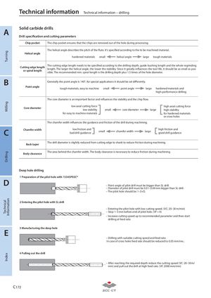
A Solid carbide drills
Drill specification and cutting parameters
| Chip pocket | The chip pocket ensures that the chips are removed out of the hole during processing. | |
| Helical angle | The helical angle describes the pitch of the flute. It's specified according to the to be mac hardened materials small helical angle large | l i hined material. tough materials |
| Cutting edge length or spiral length | The cutting edge length needs to be specified according to the drilling depth, guide bus length. The larger the helical angle, the lower the stability. Since it greatly influences the sible. The recommended min. spiral length is the drilling depth plus 1.5 times of the hole | i hing length and the whole regrinding l tool life, it should be as small as pos- diameter. |
| Point angle | Generally the point angle is 140°, for special applications it should be set differently. tough materials, easy to machine small point angle large | hardened materials and high-performance drilling |
| Core diameter | The core diameter is an important factor and influences the stability and the chip flow. low axial cutting force low stability for easy to machine materials small core diameter la | rge high axial cutting force high stability for hardened materials or cross holes |
| Chamfer width | The chamfer width influences the guidance and friction of the drill during machining. low friction and bad drill guidance small chamfer width large | high friction and good drill guidance |
| Back taper | The drill diameter is slightly reduced from cutting edge to shank to reduce friction during | machining. |
| Body clearance | The area behind the chamfer width. The body clearance is necessary to reduce friction du | ring machining. |
B
Deep hole drilling 1 Preparation of the pilot hole with 1534SP03C*
D
– Point angle of pilot drill must be bigger than SL drill. – Diameter of pilot drill must be 0.01–0.04 mm bigger than SL drill. – The pilot hole should be 1–3×D.
2 Entering the pilot hole with SL drill
E 3 Manufacturing the deep hole
– Entering the pilot hole with low cutting speed. (VC: 20–30 m/min) – Stop 1–3 mm before end of pilot hole. (Vf = 0) – Increase cutting speed up to recommended parameter and then start drilling at feed rate.
– Drilling with suitable cutting speed and feed rate. In case of cross holes feed rate should be reduced to 0.05 mm/rev..
4 Pulling out the drill
– After reaching the required depth reduce the cutting speed (VC: 20–30 m/ min) and pull out the drill at high feed rate. (Vf: 2000 mm/min)