Общий каталог ZCC-CT 2019 - страница 959
Навигация
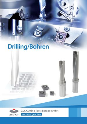 Каталог ZCC-CT сверла со сменными пластинами
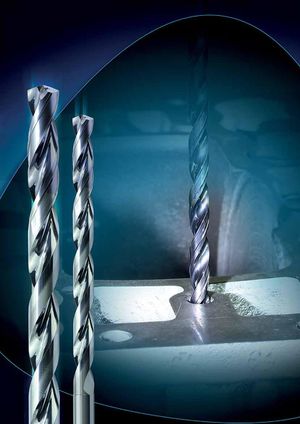 Каталог ZCC-CT сверла монолитные
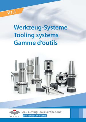 Каталог ZCC-CT оснастка
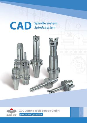 Каталог ZCC-CT расточные системы
 Каталог ZCC-CT фрезы со сменными пластинами
 Каталог ZCC-CT фрезы монолитные
- Title page
- Summary
- Turning
- Overview
- Insert overview negative inserts
- Insert overview positive inserts
- ISO code – general turning inserts
- ISO code – PCBN & PCD inserts
- Insert overview CBN & PKD
- Insert overview Ceramic
- Overview holder external
- Overview boring bars
- Explanation chipbreaker -ADF -AHF
- Explanation chipbreaker-ZM
- Explanation chipbreaker -NGF -SNR
- Grade explanation YBG101
- Grade explanation YB9320
- Grade explanationYB7315
- Simply Coloured
- Chip breaker overview negativ inserts
- Application fields of chip breakers
- Finishing
- Wiper
- Medium machining
- Roughing
- Chip breaker overview positiv inserts
- Application fields of chip breakers
- Fine-finishing
- Finishing
- Medium machining
- Roughing
- Aluminium machining
- Grade overview CVD
- Application field of grades CVD
- Grade overview PVD
- Application field of grades PVD
- Grade explanation Ceramic
- Grade explanation uncoated cermented cabidel
- Grade explanation CBN
- Grade explanation PKD
- Grade explanation Cermet
- Application felds of grade
- Conversion table metric/imperial
- Negative inserts
- CN**
- DN**
- SN**
- TN**
- VN**
- WN**
- RN**
- KN**
- Railway wheel machining
- Positiv inserts
- CC**
- CP**
- DC**
- DP**
- RC**
- SC**
- SP**
- TB**
- TC**
- TP**
- VC**
- VB**
- WC**
- CBN / PKD
- Negativ inserts
- CN**
- DN**
- SN**
- TN**
- VN**
- WN**
- Positiv inserts
- CC**
- DC**
- TC**
- VB**
- VC**
- Solide CBN
- CN**
- SN**
- WN**
- RN**
- PKD
- CC**
- DC**
- TC**
- VB**
- VC**
- Ceramic
- CN*
- DN**
- SN**
- TN**
- RN**
- WN**
- External tool holders overview
- ISO code – external tool holders
- D- Holder
- DCLNR/L Kr: 95°
- DDJNR/L Kr: 93°
- DSBNR/L Kr: 75°
- DTGNR/L Kr: 91°
- DVVNN Kr: 72°30'
- DVJNR/L Kr: 93°
- DWLNR/L Kr: 95°
- P- Holder
- PCBNR/L Kr: 75°
- PCLNR/L Kr: 95
- PDJNR/L Kr: 93°
- PDNNR/L Kr: 63°
- PSBNR/L Kr: 75°
- PSDNN Kr: 45°
- PSKNR/L Kr: 75°
- PSSNR/L Kr: 45°
- PTFNR/L Kr: 91°
- PTTNR/L Kr: 60°
- PTGNR/L Kr: 90°
- PWLNR/L Kr: 95°
- M- Halter
- MCBNR/L Kr: 75°
- MCLNR/L Kr: 95°
- MDJNR/L Kr: 93
- MDPNN Kr: 62°30'
- MSBNR/L Kr: 75
- MSRNR/L Kr: 75
- MSKNR/L Kr: 75°
- MSDNN Kr: 45°
- MTGNR/L Kr: 90°
- MTJNR/L Kr: 93°
- MTFNR/L Kr: 91°
- MVVNN Kr: 72°30'
- MVJNR/L Kr: 93°
- MWLNR/L Kr: 95°
- MRDNN
- MRGNR/L
- S- Holder
- SCACR/L Kr: 90°
- SCLCR/L Kr: 95°
- SDACR/L Kr: 90°
- SDJCR/L Kr: 93°
- SDNCN Kr: 62°30'
- SVJBR/L Kr: 93°
- SVABR/L Kr: 90°
- SVVBN Kr: 72°30'
- SVVCN Kr: 72°30'
- SVJCR/L Kr: 93°
- SSBCR/L Kr: 75°
- SSDCN Kr: 45°
- SSKCR/L Kr: 75°
- SSSCR/L Kr: 45°
- STACR/L Kr: 90°
- STFCR/L Kr: 91°
- STGCR/L Kr: 91°
- STTCR/L Kr: 60°
- SWACR/L Kr: 90°
- SRDCN
- SRGCR/L
- C- Holder
- CKJNR/L Kr: 93°
- CCLNR/L Kr: 95°
- CTJNR/L Kr: 93°
- CDJNR/L Kr: 93°
- CTUNR/L Kr: 93
- CSKNR/L Kr: 75°
- CSRNR/L Kr: 75°
- CRDNN
- CSDNN Kr: 45°
- J- Holder
- JDJNR/L Kr: 93°
- JSDNN Kr: 45°
- External tool holders – Swiss turning
- ISO code
- SCACR/L-SC Kr: 90°
- SCLCR/L-SC Kr: 95°
- SDACR/L-SC Kr: 90°
- SDHCR/L-SC Kr: 107°30'
- SDJCR/L-SC Kr: 93°
- SDNCN-SC Kr: 62°30'
- SVACR/L-SC Kr: 90°
- SVJCR/L-SC Kr: 93°
- Boring bars overview
- ISO code – boring bars
- P- boring bar
- PCLNR/L Kr: 95°
- PDSNR/L Kr: 62°30
- PDUNR/L Kr: 93°
- PSKNR/L Kr: 75°
- PTFNR/L Kr: 90°
- PWLNR/L Kr: 95°
- S- boring bar
- SCLCR/L Kr: 95°
- SDQCR/L Kr: 107°30'
- SDUCR/L Kr: 93°
- SDZCR/L Kr: 85°
- SSKCR/L Kr: 75°
- STFCR/L Kr: 91°
- SVQCR/L Kr: 107°30'
- SVUCR/L Kr: 93°
- SVQBR/L Kr: 107°30
- SVUBR/L Kr: 93°
- SCLPR/L Kr: 95°
- SDQPR/L Kr: 107°30'
- SDUPR/L Kr: 93°
- STUPR/L Kr: 93°
- SCFCR/L Kr: 90°
- SCLCR/L Kr: 95°
- Anti Vibration Boring Bar
- SCLCR/L Kr: 95°
- SCLCR/L Kr: 95°
- SDQPR/L Kr: 107°30'
- SDQCR/L Kr: 107°30'
- SDUPR/L Kr: 93°
- SDUCR/L Kr: 93°
- STUPR/L Kr: 93°
- STFCR/L Kr: 90°
- STFPR/L Kr: 90°
- SVQCR/L Kr: 107°30'
- SVUCR/L Kr: 93°
- Parting & grooving
- Overview
- Product overview
- System overview
- Chip breaker overview
- Grade overview
- System code – inserts
- ZT*D*MM
- ZP*D*MG
- ZP*S**MG
- ZP*D**MG*L/R
- ZT*D**MG
- ZT*S**MG
- ZT*D**EG grinded
- ZR*D**MG
- ZR*F**EG
- ZIMF**NM
- ZIGQ*NM
- ZR*D**LH
- ZILD**LC
- Parting & grooving holders
- System code – tool holders
- External tool holders
- Boring bars
- Blade & Clamping block
- Boring bars
- C**-Q*DR/L (from 2mm)
- C40X-Q*DR/L
- Parting & grooving tool holder (external)
- QE**R/L
- QE**SN
- QECD**R/L
- QX*D**R/L
- QE**SR/L
- QE*S**N
- QZS** (Monoblock)
- Parting & grooving tool holder (axial)
- QF**R/L
- QF**RR/LL
- QF**SRR/LL
- QF**DR/L
- QFHSDR/L
- QF**R/L
- QC - Parting & grooving system
- System code - inserts
- QC inserts
- System code - tool holder
- Grooving (external)
- Grooving (Internal)
- Threading
- Grade overview
- System code – inserts
- System overview (Sandvik compatibel R166.)
- GM - ISO metric coarse thread 60°
- Partial profile 60°
- Partial profile 55°
- Whitworth
- Unified conventional thread
- BSPT Whitworth taper pipe thread
- NPT American taper pipe thread
- NPTF dryseal American taper pipe thread
- R knuckle thread 30°
- MJ thread for aerospace
- UNJ unified screw thread
- TR metrical ISO trapezoidal thread
- ACME American national thread
- STUB-ACME thread
- API 60° thread
- API round thread
- API American buttress thread
- System overview (ThinType)
- ISO metric coarse thread 60°
- Partial profile 60
- Partial profile 55°
- Whitworth
- UN unified conventional thread
- BSPT Whitworth taper pipe thread
- NPT American taper pipe thread
- System code – tool holders (Sandvik compatibel R166.)
- Threading tool holder (Sandvik compatible R166.)
- Threading tool holder ( ISO - ThinType)
- Cutting datas
- Recommended cutting data inserts, negativ
- Recommended cutting data inserts, positiv
- Recommended cutting data inserts, Parting & grooving
- Recommended cutting data inserts, Threading inserts
- Technical informations
- Milling
- Indexable Milling
- Overview
- Produkt overview inserts
- System overview
- Facemilling
- Square shoulder milling
- Profile milling
- Slot milling
- High feed milling
- Bore milling
- T-slot milling
- Helical milling
- Champfer milling
- Indexable heads - QCH
- Chip breakers overview
- Grade overview
- System code – milling bodies
- ISO code – inserts
- System code – slot milling
- Face milling
- FMA01 Kr: 45°
- FMA02 Kr: 45°
- FMA03 Kr: 45°
- FMA04 Kr: 45° screws clamping
- FMA04 Kr: 45° wedge clamping
- FMA07 Kr: 45°
- FMA11 Kr: 45°
- FMA12 Kr: 45°
- FMD02 Kr: 67°
- FMD02 Kr: 55° (alt)
- FMD03 Kr: 60°
- FME02 Kr: 75°
- FME03 Kr: 75°
- FME04 Kr: 75°
- FMP01 Kr: 90°
- FMP02 Kr: 90°
- FMP03 Kr: 89°
- FMP12 Kr: 90°
- FMR01 round insert
- FMR02 round insert
- FMR03 round insert thick inserts
- FMR03 round insert thin inserts
- FMR04 round insert thick inserts
- FMR04 round insert thin inserts
- Square sholder milling
- EMP01
- EMP02
- EMP03
- EMP04
- EMP05
- EMP09
- EMP13
- Profile milling
- BMR01
- BMR02
- BMR03
- BMR04
- Slot milling
- SMP01
- SMP03
- SMP05
- High feed milling
- XMR01 SDMT
- XMR01 WPGT
- Bore milling
- XMP01
- T-slot milling
- TMP01
- Helical milling
- HMP01
- HMP01 EC
- Chamfer milling
- CMZ01 Kr: 30°
- CMA01 Kr: 45°
- CMD01 Kr: 60°
- Indexable heads
- QCH - XPHT
- QCH - SDMT
- QCH - WPGT
- QCH - APKT
- QCH - RD Dicke Platte
- QCH - RD Dünne Platte
- QCH - ZOHX
- Milling inserts without bodys
- HNGX
- LNE
- LNCX
- SNKN
- SPAN / SPCN
- SPMR
- SPMT
- SPGN / SPUN
- TPAN / TPCN
- TPKN
- TPMR / TPUN
- Guide for recommended cutting data – indexable milling
- Recommended cutting data
- Group 1 (FMA07/11/12, FMD02, EMP09/13)
- Group 2 (FMA01/02/03/04, FME01/02, EMP01/02/03/04)
- Group 3 (FMR01/02/03/04)
- Group 4 (BMR01/02/03/04, TMP01,CMZ01,CMA01,CMD01)
- Group 5 (SMP01/03/05)
- Group 6 (FMD03, FME04, FMP03, HMP01)
- Group 7 (XMR01, XMP01)
- Recommend feed rate
- Group 1 / 2
- Group 3
- Group 4 / 5
- Group 6 / 7
- Solid carbide milling
- Overview
- Grade overview
- System code – DIN-ISO series
- System code – JIS series
- GM - series
- 2 Flute End mill
- 5501R302GM
- 5601R302GM
- 5502R302GM
- 5602R302GM
- GM-2E
- GM-2EL
- GM-2EX
- GM-2EFP
- GM-2F
- GM-2FL
- GM-2EP
- GM-2ES
- 3 Flute End mill
- GM-3E
- GM-3EL
- 5501R303GM
- 5601R303GM
- 5502R303GM
- 5602R303GM
- 5502R453GM
- 5602R453GM
- 4 Flute End mill
- GM-4F-G
- GM-4EL-G
- GM-4FL-G
- GM-4EX-G
- GM-4E
- GM-4E-G
- GM-4EL
- GM-4EFP
- 5501R304GF
- 5601R304GF
- 5502R304GF
- 5602R304GF
- 5508R454GM
- 5602R454GM
- Multiflute End mill
- 5589R45MGFR02
- GM-6E
- GM-6EL
- 2 Flute Ball nose cutter
- 5565R302GF
- 5665R202GM
- 5566R302GF
- GM-2B
- GM-2BL
- GM-2BFP
- GM-2BS
- GM-2BP
- 4 Flute Ball nose cutter
- GM-4B
- GM-4BL
- 2 Flute Torus mill
- GM-2R
- 4 Flute Torus mill
- GM-4R
- GM-4RL
- Ripper
- 5602R303GR
- 5602R304GR
- 5602R305GR
- GM-4W
- PM - series
- 2 Flute End mill
- PM-2E
- PM-2EL
- 4 Flute End mill
- PM-4E-G
- PM-4EL-G
- PM-4EX-G
- PM-4E
- PM-4EL
- 6 Flute End mill
- PM-6E
- PM-6EL
- 2 Flute Ball nose cutter
- PM-2B
- PM-2BL
- PM-2BFP
- PM-2BC
- 4 Flute Ball nose cutter
- PM-4B
- PM-4BL
- 2 Flute Torus mill
- PM-2R
- 4 Flute Torus mill
- PM-4H
- PM-4HL
- PM-4R
- PM-4RL
- HM - series
- 2 Flute End mill
- HM-2E
- HM-2EFP
- HM-2EP
- HM-2ES
- 4 Flute End mill
- HM-4E
- HM-4EL
- HM-4EFP
- Multiflute End mill
- 5502R55MHH
- HM-6E
- HM-6EL
- 2 Flute Ball nose cutter
- HM-2B
- HM-2BL
- HM-2BFP
- HM-2BS
- HM-2BP
- 4 Flute Ball nose cutter
- HM-4B
- HM-4BL
- 4 Flute Torus mill
- HM-4R
- HM-4RF
- HM-4RP
- NM - series
- 2 Flute End mill
- 5502R402NM
- NM-2E
- NM-2EP
- 4 Flute End mill
- NM-4E
- 2 Flute Ball nose cutter
- NM-2B
- NM-2BP
- AL - series
- 2 Flute End mill
- AL-2E
- AL-2EL
- ALG-2E
- 3 Flute End mill
- AL-3E
- AL-3EL
- ALG-3E
- ALG-3E-W
- ALP-3E
- ALP-3E-W
- 4 Flute End mill
- ALP-4E
- ALP-4E-W
- Ripper
- AL-3W
- 2 Flute Ball nose cutter
- 5565R302NH
- 5566R302NH
- AL-2B
- 2 Flute Torus mill
- AL-2R-AIR
- AL-2RL-AIR
- ALG-2R
- ALG-2R-W
- 3 Flute Torus mill
- AL-3R-AIR
- AL-3RL-AIR
- HPC / HSC
- DIN - series
- End mill
- 5501R38414GM
- 5502R38414GM
- 5601R38414GM
- 5602R38414GM
- Torus mill
- 5502R38414GM-R
- 5602R38414GM-R
- UM - series
- End mill
- UM-4E
- UM-4E-W
- UM-4EL
- UM-4EL-W
- UM-4ELP-W
- UM-4EFP
- Torus mill
- UM-4R
- UM-4RL
- UM-4RFP
- VSM - series
- Endmill
- VSM-4E
- VSM-4E-C
- Torus Mill
- VSM-4R
- Deburing cutter
- 5501/5601R60*FM - 60°
- 5501/5601R90*FM - 90°
- 5601R90*FM-R - Radius
- Recommended cutting data solid carbide milling
- Guide for recommended cutting data
- Recommended cutting data GM Serie
- Recommended cutting data HM Serie
- Recommended cutting data NMSerie
- Recommended cutting data AL Serie
- Recommended cutting data PM Serie
- Recommended cutting data HPC / UM / VSM Serie
- Recommended cutting data FM Serie Deburing cutter
- Solid carbide milling group 1 / 2 / 3 / 4
- Solid carbide milling group 5 / 6 / 7 / 8
- Solid carbide milling group 9 / 10 / 11
- Technical informations milling
- Trouble shooting – milling
- General formulas
- Plunging and circular milling with insert APKT
- Plunging and circular milling with insert WPGT or SDMT
- Machining strategy – HPC/UM (HSC) milling cutters
- Form nonstandard order
- Drilling
- Indexable drills
- Products Overview
- Chip breaker overview
- Grade overview
- System code – drilling bodies
- ZTD - series
- ZTD02
- ZTD03
- ZTD04
- ZTD05
- ZD - series
- ZD03
- ISO-Code – inserts
- Insers indexable drills
- Recommended cutting data Indexable drills
- Solid carbide drills
- Product overview
- Grade overview
- System code – solid carbide drills
- SU - series
- SU(K) drill 3xD shank HA
- SU(K) drill 5xD shank HA
- SU(K) drill 8xD shank HA
- SU(K) drill 3xD shank HB
- SU(K) drill 5xD shank HB
- SU(K) drill 3xD shank HE
- SU(K) drill 5xD shank HE
- SU 3xD Step drill
- SL - series
- SL(K) drill 10xD
- SL(K) drill 12xD
- SL(K) drill 15xD
- SL(K) drill 20xD
- SL(K) drill 30xD
- SP drill 3xD (Pilot)
- ST - series
- ST drill 3xD Shank HA
- ST drill 5xD Shank HA
- ST drill 5xD Shank HB
- SH - series
- SH drill 3xD Shank HA
- SC - series
- SC drill 3xD
- SC drill 5xD
- PA - series
- PA drill 3xD
- PC - series
- PC drill 5xD
- PC drill 15xD
- NC tapping device
- SC drill – NC tapping device 90°
- SC drill – NC tapping device 120°
- Recommended cutting data – solid carbide drilling
- Recommended cutting data – solid carbide drilling
- Recommended cutting data
- Recommended feed rate
- Solid carbide reamers
- Product overview
- Grade overview
- System code – solid carbide reamers
- 3101H7 Reamer, right-hand twist
- 3102H7 Reamer, straight flute
- 3112H7 Reamer, straight flute
- 3103H7 Reamer, left-hand twist
- Recommended cutting data – Solid carbide reamers
- Recommended cutting data – Solid carbide reamers
- Recommended cutting data
- Recommended feed rate
- Solid carbide threading tools
- Product overview
- Grade overview
- System code – solid carbide threading tools
- 4122A Thread formers
- 4222A Thread formers
- 4122M Thread formers
- 4222M Thread formers
- 4201C Tap, right-hand twist
- 4202C Tap, straight flute
- 4201A Tap, right-hand twist
- 4202A Tap, straight flute
- 4111 Thread milling cutter, coated
- Recommended cutting data – Solid carbide threading tool
- Guide for recommended cutting data
- Recommended cutting data
- Recommended feed rate
- Technical information
- Form nonstandard order
- Technical information
- Comparison table materials
- Comparison table hardness and tensile strength
- Conversion table chip breakers – turning
- Conversion table grades – turning
- Conversion table grades – milling
- Examples of materials for machining groups
- Form test protocol
- Torque for screw
- Index
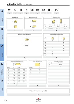
| W | C | M | X | 08 | 04 | 12 | R | – PG | |||||
| A | |||||||||||||
| 1 | 2 | 3 | 4 | 5 | 6 | 7 | 8 | 9 |
Insert shape Clearance angle Tolerance class
m W C 80° 7°
I.C S
| Code | I.C [mm] | m [mm] | S [mm] | ||||
| P | G | ±0,025 | ±0,025 | ±0,130 | |||
| S | |||||||
| B | 11° | M | ±0,05–0,13 | ±0,08–0,18 | ±0,130 |
1 2 3
Fastening features (metric) Cutting edge length l [mm] Insert shape Insert shape ≤ 65° I.C T [mm]
| l | l | ||||
| S | W | ||||
| 3,8 | 03 | ||||
| 4,3 | 04 | ||||
| C | X | Special | 5,4 | 05 |
6,35 06 6,5 06 8,0 08 8,7 08
9,252 09 12,7 12
4 5
Insert thickness S [mm] Nose radius r [mm] Rotation direction
| D | Code | Description | |
| r |
| S | R | Right |
| L | Left |
| Code | S | Code | S | Code | r |
| 00 | 0,79 | 05 | 5,56 | 04 | 0,4 |
| T0 | 0,99 | T5 | 5,95 | 08 | 0,8 |
| 01 | 1,59 | 06 | 6,35 | 12 | 1,2 |
| T1 | 1,98 | T6 | 6,75 | ||
| 02 | 2,38 | 07 | 7,94 | ||
| T2 | 2,58 | 09 | 9,52 | ||
| 03 | 3,18 | T9 | 9,72 | ||
| E T3 | 3,97 | 11 | 11,11 | ||
| 04 | 4,76 | 12 | 12,70 | ||
| T4 | 4,96 |
6 7 8
Chip breaker overview (on page C3)