Каталог Sumitomo фрезы со сменными пластинами - страница 54
Навигация
 Каталог Sumitomo инструмент для обработки канавок
 Общий каталог Sumitomo 2019 - 2020
 Каталог Sumitomo модульные системы для револьверных головок токарных станков
 Каталог Sumitomo токарные резцы (державки) для внутреннего точения
 Общий каталог Sumitomo 2018 - 2019
 Каталог Sumitomo монолитные фрезы
- H001
- H002
- H003
- H004
- H005
- H006
- H007
- H008
- H009
- H010
- H011
- H012
- H013
- H014
- H015
- H016
- H017
- H018
- H019
- H020
- H021
- H022
- H023
- H024
- H025
- H026
- H027
- H028
- H029
- H030
- H031
- H032
- H033
- H034
- H035
- H036
- H037
- H038
- H039
- H040
- H041
- H042
- H043
- H044
- H045
- H046
- H047
- H048
- H049
- H050
- H051
- H052
- H053
- H054
- H055
- H056
- H057
- H058
- H059
- H060
- H061
- H062
- H063
- H064
- H065
- H066
- H067
- H068
- H069
- H070
- H071
- H072
- H073
- H074
- H075
- H076
- H077
- H078
- H079
- H080
- H081
- H082
- H083
- H084
- H085
- H086
- H087
- H088
- H089
- H090
- H091
- H092
- H093
- H094
- H095
- H096
- H097
- H098
- H099
- H100
- H101
- H102
- H103
- H104
- H105
- H106
- H107
- H108
- H109
- H110
- H111
- H112
- H113
- H114
- H115
- H116
- H117
- H118
- H119
- H120
- H121
- H122
- H123
- H124
- H125
- H126
- H127
- H128
- H129
- H130
- H131
- H132
- H133
- H134
- H135
- H136
- H137
- H138
- H139
- H140
- H141
- H142
- H143
- H144
- H145
- H146
- H147
- H148
- H149
- H150
- H151
- H152
- H153
- H154
- H155
- H156
- H157
- H158
- H159
- H160
- H161
- H162
- H163
- H164
- H165
- H166
- H167
- H168
- H169
- H170
- H171
- H172
- H173
- H174
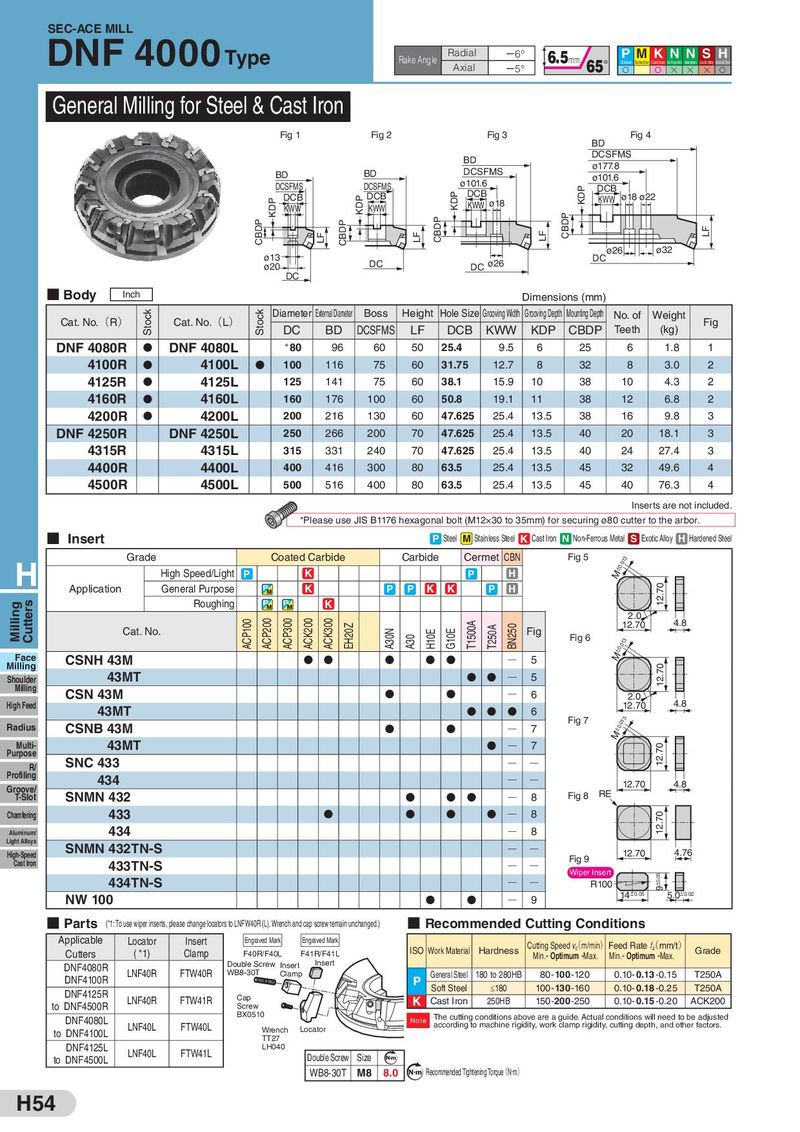
SEC-ACE MILL DNF 4000 Type Rake Angle Radial 㸫6° 6.5mm P MK N N S H Axial 㸫5° 65° Steel Stainless Steel Cast Iron Non-Ferrous Metal Aluminum Exotic Alloy Hardened Steel S S H H H S General Milling for Steel & Cast Iron Fig 1 Fig 2 Fig 3 BD Fig 4 BD DCSFMS BD DCSFMS ø177.8 BD ø101.6 ø101.6 DCSFMS DCSFMS KDP DCB KDP DCB KDP DCB KDP DCB KWW ø18 KWW ø18 ø22 KWW KWW CBDP CBDP LF CBDP LF CBDP LF LF ø13 DC ø26 ø32 ø20 DC DC ø26 DC ■ Body Inch Dimensions (mm) Cat. No.(R) Stock Cat. No.(L) Stock Diameter External Diameter Boss Height Hole Size Grooving Width Grooving Depth Mounting Depth No. of Weight Fig DC BD DCSFMS LF DCB KWW KDP CBDP Teeth (kg) DNF 4080R D DNF 4080L *80 96 60 50 25.4 9.5 6 25 6 1.8 1 4100R D 4100L D 100 116 75 60 31.75 12.7 8 32 8 3.0 2 4125R D 4125L 125 141 75 60 38.1 15.9 10 38 10 4.3 2 4160R D 4160L 160 176 100 60 50.8 19.1 11 38 12 6.8 2 4200R D 4200L 200 216 130 60 47.625 25.4 13.5 38 16 9.8 3 DNF 4250R DNF 4250L 250 266 200 70 47.625 25.4 13.5 40 20 18.1 3 4315R 4315L 315 331 240 70 47.625 25.4 13.5 40 24 27.4 3 4400R 4400L 400 416 300 80 63.5 25.4 13.5 45 32 49.6 4 4500R 4500L 500 516 400 80 63.5 25.4 13.5 45 40 76.3 4 Inserts are not included. *Please use JIS B1176 hexagonal bolt (M12×30 to 35mm) for securing ø80 cutter to the arbor. ■ Insert P Steel M Stainless Steel K Cast Iron N Non-Ferrous Metal S Exotic Alloy H Hardened Steel Grade Coated Carbide Carbide Cermet CBN Fig 5 ±0.013 H High Speed/Light P K P H M Application General Purpose K P P K K P H 12.70 Milling Cutters Roughing K ACP100 ACP200 ACP300 ACK200 ACK300 T1500A 2.0 4.8 Cat. No. EH20Z A30N H10E G10E T250A BN250 Fig 12.70 A30 Fig 6 ±0.013 Face CSNH 43M D D D D D Q 5 M Milling 12.70 Shoulder 43MT D D Q 5 Milling CSN 43M D D Q 6 2.0 4.8 High Feed 43MT D D D 6 12.70 Radius CSNB 43M D D Q 7 Fig 7 ±0.013 M Multi- 43MT D Q 7 12.70 Purpose SNC 433 R/ Q Q Profiling 434 Q Q Groove/ 12.70 4.8 T-Slot SNMN 432 D D D Q 8 Fig 8 RE Chamfering 433 D D D D Q 8 12.70 Aluminum/ 434 Q 8 Light Alloys SNMN 432TN-S High-Speed Q Q 12.70 4.76 Cast Iron 433TN-S Q Q Fig 9 Wiper Insert ±0.05 9 434TN-S Q Q R100 NW 100 D D Q 9 14±0.05 5.0±0.02 ■ Parts (*1: To use wiper inserts, please change locators to LNFW40R (L). Wrench and cap screw remain unchanged.) ■ Recommended Cutting Conditions Applicable Locator Insert Engraved Mark Engraved Mark Cutting Speed v(c m/min) Feed Rate f(z mm/t) Cutters ( *1) Clamp F40R/F40L F41R/F41L ISO Work Material Hardness Min.- Optimum -Max. Min.- Optimum -Max. Grade DNF4080R Double Screw Insert Insert DNF4100R LNF40R FTW40R WB8-30T Clamp General Steel 180 to 280HB 80- 100 -120 0.10- 0.13 -0.15 T250A P Soft Steel ≤180 100- 130 -160 0.10- 0.18 -0.25 T250A DNF4125R LNF40R FTW41R Cap K Cast Iron 250HB 150-200-250 0.10- 0.15 -0.20 ACK200 to DNF4500R Screw DNF4080L BX0510 Note The cutting conditions above are a guide. Actual conditions will need to be adjusted to DNF4100L LNF40L FTW40L Wrench Locator according to machine rigidity, work clamp rigidity, cutting depth, and other factors. TT27 DNF4125L LNF40L FTW41L LH040 to DNF4500L Double Screw Size Nm WB8-30T M8 8.0 N m Recommended Tightening Torque(N・m) H54