Общий каталог Yamawa 2022 - 2023 - страница 934
Навигация
 Краткое руководство Yamawa по каталогам
 Общий каталог Yamawa 2021
 Каталоги Yamawa твердосплавные метчики для закаленной стали
 Обший каталог Yamawa 2016 - 2017
- How to Read the General Catalog
- Z-PRO Product System
- New System table of taps for steels, blind hole use(low and middle speed range)
- New System table of taps for steels, blind hole use(Middle and High speed range)
- New System table of taps for steels, blind hole use(low and middle speed range)
- New System table of taps for steels, blind hole use(Middle and High speed range)
- New System table of taps for stainless steels, blind hole use
- New System table of taps for stainless steels, through hole use
- New System table of taps for non-ferrous materials, blind hole use
- New System table of taps for non-ferrous materials, through hole use
- New System table of roll taps for steels
- New System table of roll taps for non-ferrous materials
- YAMAWAPRODUCT LINE-UPS
- ①Spiral Fluted Tap Series for blind hole
- ②Spiral Fluted Tap Series for through hole
- ③Spiral Pointed Tap Series for through hole
- ④Hand Tap Series
- ⑤Cemented Carbide Tap Serie
- ⑥Roll Tap Series
- ⑦Special Thread Taps / Simple Inspection Tools
- ⑧Pipe Tap Series
- ⑨Thread Mills / Premium Thread Mills
- ⑩Dies
- ⑪Center Drills/Centering Tools
- ①Spiral Fluted Tap Series for blind hole
- ②Spiral Fluted Tap Series for through hole
- ③Spiral Pointed Tap Series for through hole
- ④Hand Tap Series
- ⑤Cemented Carbide Tap Series
- ⑥Roll Tap Series
- ⑦Special Thread Taps / Simple Inspection Tools
- ⑧Pipe Tap Series
- ⑩Dies
- ①Spiral Fluted Tap Series for blind hole
- ②Spiral Fluted Tap Series for through hole
- ③Spiral Fluted Tap Series for through hole
- ④Hand Tap Series
- ⑤Cemented Carbide Tap Series
- ⑥Roll Tap Series
- ⑦Special Thread Taps / Simple Inspection Tools
- ⑧Pipe Tap Series
- ⑩Dies
- ① SPIRAL FLUTED TAPSERIES FOR BLIND HOLE
- Selection chart of taps
- VUSP Z-PRO Coated Spiral Fluted Taps
- VUSP Z-PRO Coated Spiral Fluted Taps
- VUSP Z-PRO Coated Spiral Fluted Taps
- VUSP 1.5P Z-PRO Coated Spiral Fluted Taps 1.5P
- VUSP 1.5P Z-PRO Coated Spiral Fluted Taps 1.5P
- VUSP E Z-PRO Coated Spiral Fluted Taps E(1.5P)
- VUSP CH Z-PRO Coated Spiral Fluted Taps with Coolant Through Hole
- VUSP CH Z-PRO Coated Spiral Fluted Taps with Coolant Through Hole
- VUSP CH Z-PRO Coated Spiral Fluted Taps with Coolant Through Hole
- HVSP Z-PRO Spiral fluted Taps for Forged Parts in the Heavy Metalworking Industry
- HVSP Z-PRO Heavy Industry Spiral Fluted Tap for Large Parts Processing
- HVSP Z-PRO Heavy Industry Spiral Fluted Tap for Large Parts Processing
- MHSP Z-PRO Spiral Taps for Medium Hard Carbon Steels
- MHSP Z-PRO Spiral Taps for Medium Hard Carbon Steels
- SP Spiral Fluted Taps
- SP Spiral Fluted Taps
- SP Spiral Fluted Taps
- +SP Plus Series Spiral Fluted Taps
- SP 1.5P Spiral Fluted Taps 1.5P
- IS PSpiral Fluted Taps for General Purpose
- IS PSpiral Fluted Taps for General Purpose
- SP OX Spiral Fluted Taps,Oxidized
- SP OX Spiral Fluted Taps,Oxidized
- SP OX Spiral Fluted Taps, Oxidized
- SP Spiral Fluted Taps for Alloy Steels
- SP LH Spiral Fluted Taps for Left Hand Threads
- SP LH Spiral Fluted Taps for Left Hand Threads
- SP V Spiral Fluted Taps, Coated
- AU+SP Plus Series Spiral Fluted Taps,Optimum Coating for the Tapping
- AU+SP Plus Series Spiral Fluted Taps,Coated
- AU+SP Plus Series Spiral Fluted Taps, Coated
- LS-SP Long Shank Spiral Fluted Taps
- LS-SP OX Long Shank Oxidized Spiral Tap
- LS-SP LH Long Shank Spiral Fluted Taps for Left Hand Threads
- LS-SP V Long Shank Spiral Fluted Taps, Coated
- LS-SP-K Long Shank Spiral Fluted Taps with Long Neck
- SU+SP SU-SP Spiral Fluted Taps for Stainless Steels
- ZELX SS SP Spiral Fluted Taps for Stainless Steels
- SP-VA Spiral Fluted Taps for Stainless Steels
- SP+VA Spiral Fluted Taps for Stainless Steels
- SP-VA Spiral Fluted Taps for Stainless Steels, Coated
- SU2-SP Spiral Fluted Taps for Tough Stainless Steels
- SU2-SP Spiral Fluted Taps for Tough Stainless Steels
- SU-S-SP Spiral Fluted Taps for Stainless Steels, Deep Hole Use
- LS-SU-S-SP Long Shank Spiral Fluted Taps for Stainless Steels, Deep Hole Use
- ZELX SS SP 6" Long Shank Spiral Fluted Taps for Stainless Steels
- S-SP Short Spiral Fluted Taps, Deep Hole Use
- SP-BLF Spiral Fluted Taps, Deep Hole Use
- SP-BLF OX Spiral Fluted Taps, Deep Hole Use, Oxidized
- SP-BLF Spiral Fluted Taps, Deep Hole Use(Coated)
- E-SP Spiral Fluted Taps for Soft Structural Steels
- HC+SP HC-SP Spiral Fluted Taps for High Carbon Steels
- HC+SP OX HC-SP OX Spiral Fluted Taps for High Carbon Steels, Oxidized
- AL+SP AL-SP Spiral Fluted Taps for Aluminum
- AL-SP 1.5P Spiral Fluted Taps for Aluminum 1.5P
- AL-SP Spiral Fluted Taps for Aluminum
- AL+SP AL-SP Spiral Fluted Taps for Aluminum
- ALS-SP Spiral Fluted Taps for Aluminum
- LO-SP Low Spiral Fluted Taps
- LO-SP Low Spiral Fluted Taps for Alloy Steels
- LO-SP Low Spiral Fluted Taps
- LO-SP OX Low Spiral Fluted Taps, OxidizedDIN
- LS-LO-SP Long Shank Low Spiral Fluted Taps
- ZET-B Spiral Fluted Taps for Titanium Alloys
- ZELX TI SP Spiral Fluted Taps for Titanium Alloys
- ZET-B Spiral Fluted Taps for Titanium Alloys
- ZEN-B Spiral Fluted Taps for Nickel Base Alloys
- ZELX NI SP Spiral Fluted Taps for Nickel Base Alloys
- ZEN-B Spiral Fluted Taps for Nickel Base Alloys
- PM-SP Spiral Fluted Taps for Hard-to-Machine Materials
- PM-SP Spiral Fluted Taps for Hard-to-Machine Materials
- PH-SP Spiral Fluted Taps for Hard-to-Machine Materials
- LS-PM-SP Long Shank Spiral Fluted Taps for Hard-to-Machine Materials
- F-SP Spiral Fluted Taps for High Speed Tapping
- ZELX FR Spiral Fluted Taps for High Speed Tapping
- F-SP Spiral Fluted Taps for High Speed Tapping
- LS-F-SP Long Shank Spiral Fluted Taps for High Speed Tapping
- HFIHS For Ultra Fast Tapping, Vertical Use. Spiral Fluted Taps for Steels
- HFIHS For Ultra Fast Tapping, Vertical Use. Spiral Fluted Taps for Steels
- HFISP For Ultra Fast Tapping, Horizontal Use. Low Spiral Fluted Taps for Steels
- HFISP For Ultra Fast Tapping, Horizontal Use. Low Spiral Fluted Taps for Steels
- HFAHS For Ultra Fast Tapping, Vertical Use. Spiral Fluted Taps for Aluminum
- HFAHS For Ultra Fast Tapping, Vertical Use, Spiral Fluted Taps for Aluminum
- HFASP For Ultra Fast Tapping, Horizontal Use. Low Spiral Fluted Taps for Alum
- HFASP For Ultra Fast Tapping, Horizontal Use, Low Spiral Fluted Taps for Aluminum
- HDISP For Dry Tapping, Blind Hole Use. Spiral Fluted Taps for Steels
- HDISP For Dry Tapping, Blind Hole Use, Spiral Fluted Taps for Steels
- HDASP For Dry Tapping, Blind Hole Use. Spiral Fluted Taps for Aluminum
- HDASP For Dry Tapping, Blind Hole Use, Spiral Fluted Taps for Aluminum
- MC-SP Spiral Fluted Taps with Internal Coolant Hole
- XSP X Series Spiral Fluted Taps
- AUXSP X Series Spiral Fluted Taps, Coated
- AUXSP X SeriesSpiral Fluted Taps, Coated
- SUXSP X Series Spiral Fluted Taps for Stainless Steels
- ② SPIRAL FLUTED TAP SERIESFOR THROUGH HOLE
- Selection chart of taps
- MHSL Z-PROSpiral Fluted Taps for Carbon Steels of Medium Hardness,Through Hole Use (with LH Spiral Flutes)
- MHSL Spiral Fluted Taps for Carbon Steels of Medium Hardness,Through Hole Use (with LH Spiral Flutes)
- MHSL Z-PRO Spiral Fluted Taps for Carbon Steels of MediumHardness, Through Hole Use (with LH Spiral Flutes)
- MHSL Z-PRO Spiral Fluted Taps for Carbon Steels of MediumHardness, Through Hole Use( with LH Spiral Flutes)
- LKSL Z-PRO Long Neck Spiral Fluted Tap for Through Hole
- LKSL XL Z-PRO Extra-Long Neck Spiral Fluted Tap for Through Hole
- AU+SL Spiral Fluted Taps, Coated, Through Hole Use(with LH Spiral Flutes)
- AU+SL Spiral Fluted Taps, Coated, Through Hole Use( with LH Spiral Flutes
- SU+SL Spiral Fluted Taps for Stainless Steels, Through Hole Use(with LH Spiral Flutes)
- SL+VA Spiral Fluted Taps for Stainless Steels, Through Hole Use(with LH Spiral Flutes)
- ZET-P Spiral Fluted Taps for Titanium Alloys, Through Hole Use (with LH Spiral Flutes)
- ZELX TI LHSP Spiral Fluted Taps for Titanium Alloys, Through Hole Use(with LH Spiral Flutes)
- ZET-P Spiral Fluted Taps for Titanium Alloys, Through Hole Use( with LH Spiral Flutes)
- F-SL Spiral Fluted Taps for High Speed Tapping, Through Hole Use (with LH Spiral Flutes)
- ZELX FR LHSP Spiral Fluted Taps for High Speed Tapping, Through Hole Use( with LH Spiral Flutes)
- F-SL Spiral Fluted Taps for High Speed Tapping, Through Hole Use( with LH Spiral Flutes)
- LS-F-SL Long Shank Spiral Fluted Taps for High Speed Tapping, Through Hole Use (with LH Spiral Flutes)
- HDISL Spiral Fluted Taps for Steels, for Dry Tapping and for UltraHigh Speed Tapping, Through Hole Use (with LH Spiral Fluted)
- HDISL Spiral Fluted Taps for Steels, for Dry Tapping and for UltraHigh Speed Tapping, Through Hole Use( with LH Spiral Flutes)
- XSL X Series Spiral Fluted Taps, Through Hole Use (with LH Spiral Flutes)
- AUXSL X Series Spiral Fluted Taps, Coated, Through Hole Use (with LH Spiral Flutes)
- AUXSL X Series Spiral Fluted Taps, Coated, Through Hole Use( with LH Spiral Flutes
- SUXSL X Series Spiral Fluted Taps for Stainless Steels, Through Hole Use (with LH Spiral Flutes)
- ③ SPIRAL POINTEDTAP SERIESFOR THROUGH HOLE
- Selection chart of taps
- VUPO Z-PRO Coated Spiral Pointed T
- VUPO Z-PRO Coated Spiral Pointed Taps
- VUPO Z-PRO Coated Spiral Pointed Taps
- PO Spiral Pointed Taps
- PO Spiral Pointed Taps
- PO Spiral Pointed Taps
- +PO Plus Series Spiral Pointed Taps
- IPO Spiral Pointed Taps for General Purpose
- IPO Spiral Pointed Taps for General Purpose
- PO OX Spiral Pointed Taps, Oxidized
- PO OX Spiral Pointed Taps, Oxidized
- PO OX Spiral Pointed Taps, Oxidized
- PO LH Spiral Pointed Taps for Left Hand Threads
- PO V Spiral Pointed Taps, Coated
- PO VSpiral Pointed Taps, Coated
- LS-PO Long Shank Spiral Pointed Taps
- LS-PO V Long Shank Spiral Pointed Taps, Coated
- LS-PO-K Long Shank Spiral Pointed Taps with Long Neck
- SU+PO SU-PO Spiral Pointed Taps for Stainless Steels
- ZELX SS PO Spiral Pointed Taps for Stainless Steels
- PO-VA Spiral Pointed Taps for Stainless Steels
- PO-VA Spiral Pointed Taps for Stainless Steels, Coated
- LS-SU-S-PO Long Shank Short Spiral Pointed Taps for Stainless Steels
- ZELX SS PO 6" Long Shank Spiral Pointed Taps for Stainless Steels
- S-PO Short Spiral Pointed Taps for Deep Hole Use
- HC+PO HC-PO Spiral Pointed Taps for High Carbon Steels
- HC-PO OX Oxidized Spiral Pointed Taps for High Carbon Steels
- AL-PO Spiral Pointed Taps for Aluminum
- EH-PO Spiral Pointed Taps for Hard-to-Machine Materials
- EH-PO Spiral Pointed Taps for Hard-to-Machine Materials
- ZEN-P Spiral Pointed Taps for Nickel Base Alloys
- ZELX NI PO Spiral Pointed Taps for Nickel Base Alloys
- ZEN-P Spiral Pointed Taps for Nickel Base Alloys
- PM-PO Spiral Pointed Taps for Hard-to-Machine Materials
- PM-PO Spiral Pointed Taps for Hard-to-Machine Materials
- LS-PM-PO Long Shank Spiral Pointed Taps for Hard-to-Machine Materials
- MC-PO Spiral Pointed Taps with Internal Coolant
- ④ HAND TAP SERIES
- Selection chart of taps
- HT Hand Taps
- HT Hand Taps
- HT Hand Taps
- IHT Hand Taps for General Purpose
- IHT Hand Taps for General Purpose
- HT OX Hand Taps, Oxidized
- HT LH Hand Taps for Left Hand Threads
- LS-HT Long Shank Hand Taps
- LS-HT LH Long Shank Hand Taps for Left Hand Threads
- LS-HT V Long Shank Hand Taps, Coated
- SU-HT Hand Taps for Stainless Steels
- FC-HT Hand Taps for Cast Irons
- HT-CI Hand Taps for Cast Irons
- GG-HT Hand Taps for Cast Irons
- GG-HT Hand Taps for Cast Irons, Coated
- GGST Z-PRO Straight Fluted Taps for Cast Irons
- GGST CH Z-PRO Straight Fluted Taps for Cast Irons with Coolant Through Hole,Blind Hole Use
- GG-HT-OH Hand Taps for Cast Irons with Internal Coolant Hole
- GG-HT-OH Hand Taps for Cast Irons with Internal Coolant Hole, Coated
- LA-HT Hand Taps for Die Cast Materials
- LA-HT Hand Taps for Die Cast Materials
- AXE-HT AXE Hand Taps
- AXE-HT AXE Hand Taps
- AXE-HT AXE Hand Taps
- MG-HT Hand Taps with Short Chamfer for Magnesium Alloy Castings
- PL1 Hand Taps for Plastics
- EH-HT Hand Taps for Hard-to-Machine Materials
- EH-HT Hand Taps for Hard-to-Machine Materials
- ZELX MOLD Hand Taps for Hard-to-Machine Materials
- EH-HT Hand Taps for Hard-to-Machine Materials
- RE-HT Hand Tap for Thread Repair
- MS+TR Hand Tap for Miniature Threads
- MC-HT Hand Taps with Internal Coolant Hole
- ⑤ CEMENTED CARBIDETAP SERIES
- Selection chart of taps
- N-CT LA Carbide Taps for Light Alloys
- ZELX CARB AL Carbide Taps for Light Alloys
- CT LA Carbide Taps for Light Alloys
- N-CT FC Carbide Taps for Cast Irons
- ZELX CARB CI Carbide Taps for Cast Irons
- LS-N-CT Long Shank Carbide Taps
- N-CT-SP Spiral Fluted Carbide Taps
- N-CT-PO Spiral Pointed Carbide Taps
- EH-CT Carbide Taps for Hard Materials
- EH-CT Carbide Taps for Hard Materials
- UH-CT Carbide taps for ultra hard materials
- UH-CT Carbide taps for ultra hard materials
- HFACT-P Carbide Taps for Ultra Fast Tappings, Through Hole Use, for Aluminum
- HFACT-B Carbide Taps for Ultra Fast Tappings, Blind Hole Use, for Aluminum
- HFICT-P Carbide Taps for Ultra Fast Tappings, Through Hole Use, for Cast Irons
- HFICT-B Carbide Taps for Ultra Fast Tappings, Blind Hole Use, for Cast Irons
- ACHSP Spiral Fluted Tap for Aluminum Casting
- MC-AD-CT Carbide Taps with Oil Hole
- ⑥ ROLL TAP SERIES
- Selection chart of taps
- MHRZ Z-PRO Roll Taps for Medium Hardness Carbon Steels
- MHRZ Roll Taps for Medium Hardness Carbon Steels
- MHRZ Z-PRO Roll Taps for Medium Hardness Carbon Steels
- MHRZ Z-PRO Roll Taps for Medium Hardness Carbon Steels
- N+RZ N-RZ Roll Taps for Steels
- N-RZ Roll Taps for Steels
- N+RZ N-RZ Roll Taps for Steels
- LS-N-RZ Long Shank Roll Taps for Steels
- N+RS N-RS Roll Taps for Non-Ferrous Materials
- N-RS Roll Taps for Non-Ferrous Materials
- N+RS N-RS Roll Taps for Non-Ferrous Materials
- LS-N-RS Long Shank Roll Taps for Non-Ferrous Materials
- R+V Roll Taps, Coated
- OL+RZ OL-RZ Roll Taps for Dry Tapping, Coated
- OL-RZ Roll Taps for Dry Tapping, Coated
- OL+RZ Roll Taps for Dry Tapping, Coated
- HP+RZ HP-RZ High Performance Roll Taps, Coated
- HP-RZ High Performance Roll Taps, Coated
- HP+RZ HP-RZ High Performance Roll Taps, Coated
- SC-TL-RZ Torqueless Roll Taps with Short Chamfer
- SURZ SU Roll Taps
- MS+RS Roll Taps for Miniature Threads
- HPsRZ High Performance Roll Taps for Miniature Threads
- R-Y Roll Taps for Thin Soft Structural Steel Sheets
- R-D Roll Taps for General Purpose
- R-D Roll Taps for General Purpose, Coated
- R-D Roll Taps for General Purpose, Coated
- ⑦ SPECIAL THREAD TAPS /SIMPLE INSPECTION TOOLS
- Selection chart of taps
- AL-HT STI Hand Taps for Aluminum Materials (for Helical Coil Wire Screw Thread Inserts)
- HT STI Hand Taps for Helical Coil Wire Screw Thread Inserts
- HT OX STI Hand Taps for Helical Coil Wire Screw Thread Inserts, Oxided
- AL-SP STI Spiral Fluted Taps for Aluminum Materials (for Helical Coil Wire Screw Thread Inserts)
- SP STI Spiral Fluted Taps for Helical Coil Wire Screw Thread Inserts
- SP OX STI Spiral Fluted Taps for Helical Coil Wire Screw Thread Inserts, Oxided
- ZELX NI SP STI Spiral Fluted Taps for Helical Coil Wire Screw Thread Inserts and for Nickel Base Alloys
- AL-PO STI Spiral Pointed Taps for Aluminum Materials (for Helical Coil Wire Screw Thread Inserts)
- PO STI Spiral Pointed Taps for Helical Coil Wire Screw Thread Inserts
- PO OX STI Spiral Pointed Taps for Helical Coil Wire Screw Thread Inserts, Oxidized
- ZELX NI PO STI Spiral Pointed Taps for Helical Coil Wire Screw Thread Inserts and for Nickel Base Alloys
- N-RS STI Roll Taps for Nonferrous Materials (for Helical Coil Wire Screw Thread Inserts)
- N-CT LA STI Carbide Hand Taps for Light Alloys (for Helical Coil Wire Screw Thread Inserts)
- NT Nut Taps
- HT TRI Hand Taps for Tripod Threads
- SP TRI Spiral Fluted Taps for Tripod Threads
- RLS-HT Hand Taps for Camera Release Threads
- HT TV Hand Taps for Automobile Tire Valve Threads
- HT CTV Hand Taps for Bicycle Tire Valve Threads
- HT CTC Hand Taps for Steel Conduit Threads
- HT CTG Hand Taps for Thick Steel Conduit Threads
- HT Pg Hand Taps for Steel Conduit Threads
- HT BC Hand Taps for Bicycle Threads
- HT MST Hand Tap for Microscope Objective Lens
- SL Tr Spiral Flute Tap for Through Hole for Trapezoidal Threads
- SL LH Tr A Spiral Flute Left Hand Trapezoidal Thread Tap Spiral Tap
- SIT Simple ThreadInspection Tools
- SITD Simple Thread Inspection Tools,Tandem Type
- CHECK PINS
- CPC-S Check Pins for Bored Hole in Thread Cut Tapping (Straight Type)
- CPC-T Check Pins for Bored Holes in Thread Cut Tapping (Taper Type)
- CPR-S Check Pins for Bored Hole in Thread Form Tapping (Straight Type)
- CPR-T Check Pins for Bored Holes in Thread Form Tapping (Taper Type)
- CPR-Y Check-Pins for Bored Holes in Thread Form Tapping for R-Y Taps.
- SA Shank Adjusters
- ITRD Broken Tap Removal Tools
- ⑧ PIPE TAP SERIES
- Selection chart of taps
- AUSP Rc Z-PRO Coated Spiral Fluted Taps for Taper Pipe Threads
- AUSP Rp Z-PRO Coated Spiral Fluted Taps for Parallel Pipe Threads
- AUSP G Z-PRO Coated Spiral Fluted Taps for Parallel Pipe Threads
- Rc Hand Taps for Taper Pipe Threads
- PT Hand Taps for Taper Pipe Threads, Long (ℓg) Type
- PT LH Hand Taps for Taper Pipe Threads Long (ℓg) Type for LH Threads
- PT-X X Series Hand Taps for Taper Pipe Threads Short (ℓg) Type
- S-PT Hand Taps for Taper Pipe Threads Short (ℓg) Type
- S-PT LH Hand Taps for Taper Pipe Threads Short (ℓg) Type for LH Threads
- LS-PT Long Shank Hand Taps for Taper Pipe Threads Long (ℓg) Type
- LS-S-PT Long Shank Hand Taps for Taper Pipe Threads, Short (ℓg) Type
- SP-PT Spiral Fluted Taps for Taper Pipe Threads, Long (ℓg) Type
- SP-S-PT Spiral Fluted Taps for Taper Pipe Threads Short (ℓg) Type
- SP-PT-X X Series Spiral Fluted Taps for Taper Pipe Threads Short (ℓg) Type
- LS-SP-PT Long Shank Spiral Fluted Taps for Taper Pipe Threads, Long (ℓg) Type
- LS-SP-S-PT Long Shank Spiral Fluted Taps for Taper Pipe Threads, Short (ℓg) Type
- INT-PT Interrupted Taps for Taper Pipe Threads, Long (ℓg) Type
- INT-S-PT Interrupted Taps for Taper Pipe Threads, Short (ℓg) Type
- LS-INT-PT Long Shank Interrupted Taps for Taper Pipe Threads, Long (ℓg) Type
- LS-INT-S-PT Long Shank Interrupted Taps for Taper Pipe Threads, Short (ℓg) Type
- LC-PT Hand Taps for Taper Pipe Threads Long (ℓg) Type, for Low Carbon Steels
- LC-S-PT Hand Taps for Taper Pipe Threads Short (ℓg) Type, for Low Carbon Steels
- SU-PT Hand Taps for Taper Pipe Threads Long (ℓg) Type, for Stainless Steels
- SU-S-PT Hand Taps for Taper Pipe Threads Short (ℓg) Type, for Stainless Steels
- SU-SP-PT Spiral Fluted Taps for Taper Pipe Threads, Long (ℓg) Type for Stainless Steels
- SU-SP-S-PT Spiral Fluted Taps for Taper Pipe Threads Short (ℓg) Type for Stainless Steels
- FC-PT Hand Taps for Taper Pipe Threads, Long (ℓg) Type, for Cast Irons
- FC-S-PT Hand Taps for Taper Pipe Threads, Short (ℓg) Type, for Cast Irons
- CT-PT Carbide Taps for Taper Pipe Threads, Long (ℓg) Type, for Cast Irons
- CT-S-PT Carbide Taps for Taper Pipe Threads, Short (ℓg) Type, for Cast Irons
- Rp Hand Taps for Parallel Pipe Threads
- PS Hand Taps for Parallel Pipe Threads
- PS LH Hand Taps for Parallel Pipe Threads, for LH Threads
- LS-PS Long Shank Hand Taps for Parallel Pipe Threads
- SP-PS Spiral Fluted Taps for Parallel Pipe Threads
- LS-SP-PS Long Shank Spiral Fluted Taps for Parallel Pipe Threads
- FC-PS Hand Tap for Parallel Pipe Threads in Cast Irons
- CT-PS Carbide Taps for Parallel Pipe Threads
- G Hand Taps for Parallel Pipe Threads
- HT G Hand Taps for Parallel Pipe Threads
- GG-HT G Hand Taps for Parallel Pipe Threads, for Cast Irons
- GGST G Z-PRO Straight Fluted Taps for Parallel Pipe Threads, for Cast Irons
- GG-HT G Hand Taps for Parallel Pipe Threads, for Cast Irons (Coated)
- EH-HT G Hand Taps for Parallel Pipe Threads, for Hard-to-Machine Materials
- SP G Spiral Fluted Taps for Parallel Pipe Threads
- SP OX G Spiral Fluted Taps for Parallel Pipe Threads, Oxidized
- SP V G Spiral Fluted Taps for Parallel Pipe Threads, Coated
- SP-VA G Spiral Fluted Taps for Parallel Pipe Threads, for Stainless Steels
- SU2-SP G Spiral Fluted Taps for Parallel Pipe Threads, for Tough Stainless Steels
- LO-SP G Low Spiral Fluted Taps for Parallel Pipe Threads
- LO-SP OX G Low Spiral Fluted Taps for Parallel Pipe Threads, Oxidized
- PH-SP G Spiral Fluted Taps for Parallel Pipe Threads, for Hard-to-Machine Materials
- PO G Spiral Pointed Taps for Parallel Pipe Threads
- PO OX G Spiral Pointed Taps for Parallel Pipe Threads, Oxidized
- PO V G Spiral Pointed Taps for Parallel Pipe Threads, Coated
- PO-VA G Spiral Pointed Taps for Parallel Pipe Threads, for Stainless Steels
- R-D G Roll Taps for Parallel Pipe Threads, for General Purpose
- R-D G Roll Taps for Parallel Pipe Threads, for General Purpose, Coated
- PF Hand Taps for Parallel Pipe Threads
- PF LH Hand Taps for Parallel Pipe Threads, for LH Threads
- LS-PF Long Shank Hand Taps for Parallel Pipe Threads
- SP-PF Spiral Fluted Taps for Parallel Pipe Threads
- LS-SP-PF Long Shank Spiral Fluted Taps for Parallel Pipe Threads
- SU-PF Hand Taps for Parallel Pipe Threads, for Stainless Steels
- SU-SP-PF Spiral Fluted Taps for Parallel Pipe Threads, for Stainless Steels
- FC-PF Hand Taps for Parallel Pipe Threads, for Cast Irons
- CT-PF Carbide Taps for Parallel Pipe Threads
- NPT Hand Taps for American Taper Pipe Threads
- NPT Hand Taps for American Taper Pipe Threads
- ZELX MOLD NPT Hand Taps for Hard-to-Machine Materials For American Taper Pipe Threads
- NPT-CI Hand Taps for American Taper Pipe Threads for Cast Irons
- S-NPT Hand Taps for American Taper Pipe Threads, Short (ℓg) Type
- LS-NPT Long Shank Hand Taps for American Taper Pipe Threads
- SP-NPT Spiral Fluted Taps for American Taper Pipe Threads
- ZELX SS NPT Taps for American Taper Pipe Threads
- LS-SP-S-NPT Long Shank Spiral Fluted Taps for American Taper Pipe Threads, Short (ℓg) Type
- INT-NPT Interrupted Taps for American Taper Pipe Threads
- INT-NPT Interrupted Taps for American Taper Pipe Threads
- INT-S-NPT Interrupted Taps for American Taper Pipe Threads, Short (ℓg) Type
- NPTF Hand Taps for American Dryseal Taper Pipe Threads
- NPTF Hand Taps for American Dryseal Taper Pipe Threads
- NPTF-CI Hand Taps for American Dryseal Taper Pipe Threads, for Cast Irons
- ZELX SS NPTF Taps for American Dryseal Taper Pipe Threads
- LS-NPTF Long Shank Hand Taps for American Dryseal Taper Pipe Threads
- NPS Hand Taps for American Parallel Pipe Threads
- NPS Hand Taps for American Parallel Pipe Threads
- NPSF Hand Taps for American Dryseal Parallel Pipe Threads
- NPSFHand Taps for American Dryseal Parallel Pipe Threads
- ⑨ THREAD MILLS /PREMIUM THREAD MILLS
- Selection chart of Thread Mills
- PRML Z-PRO Premium Thread Mills
- PRML TI Z-PRO Premium Thread Mills for Heat-Resistant Alloys
- MC-CSLC Carbide Thread Mills for Metric Internal Threads
- MC-CSLC Carbide Thread Mills for Taper Pipe Threads
- MC-CSLC Carbide Thread Mills for Parallel Pipe Threads
- MC-HLC Thread Mills for Metric Internal Threads
- MC-HLC Thread Mills for Taper Pipe Threads
- MC-HLC Thread Mills for Parallel Pipe Threads
- ⑩ DIES
- D Solid Round Dies
- D LH Solid Round Dies for Left Hand Threads
- D PT Solid Round Dies for Taper Pipe Threads
- D PT LH Solid Round Dies for Taper Pipe Threads, for Left Hand Threads
- D PF Solid Round Dies for Parallel Pipe Threads
- D PF LH Solid Round Dies for Parallel Pipe Threads, for Left Hand Threads
- D NPT Solid Round Dies for American Taper Pipe Threads
- D NPTF Solid Round Dies for American Dryseal Taper Pipe Threads
- D NPSM Solid Round Dies for American Parallel Pipe Threads
- DPO Spiral Pointed HSS Round Dies
- DPO Spiral Pointed HSS Round Dies
- SP-D Spiral Fluted HSS Round Dies
- HS-D HSS Round Dies for Auto Lathe, for Stainless Steel
- MS-RS-D RS-D Rolling Dies
- N-RSD New Rolling Dies
- RD-DA Die Attachment (Designed Specially for Solid Round Dies)
- RD-DA Die Attachment (Designed Specially for Solid Round Dies)
- ⑪ CENTER DRILLS /CENTERING TOOLS
- CESA High Helix Center Drills-JIS Type A 60°
- CE-S High Helix Center Drills-Type A 60°
- CE-S(I) High Helix Center Drills-Type A 60°, (Old JIS Type 1 )
- CD-S Low Helix Center Drills-Type A 60°
- CD-S(I) Low Helix Center Drills-Type A 60°, (Old JIS Type 1 )
- CD-S LH Low Helix Center Drills-Type A 60°, Left Hand Cut
- CE-S V High Helix Center Drills-Type A 60°, Coated
- CE-S V(I) High Helix Center Drills-Type A 60°, Coated, (Old JIS Type 1 )
- CD-S V Type A Low Helix Coated 60° Center Hole Drill
- CD-S V(I) Coating Low Helix A Type 60° Center Hole Drill Former JIS Type 1
- C-CD-S Carbide Center Drills-Type A 60°
- CE-SL Long Shank High Helix Center Drills-Type A 60°
- CD-SL Long Shank Low Helix Center Drills-Type A 60°
- CE-SL V Long Shank High Helix Center Drills-Type A 60°, Coated
- CD-SL V Long Shank Low Helix Center Drills-Type A 60°, Coated
- C-CD-SL Long Shank Low Helix Carbide Center Drills-Type A 60°
- CEQA High Helix Center Drills-JIS Type A 90°
- CE-Q High Helix Center Drills-Type A 90°
- CD-Q Low Helix Center Drills-Type A 90°
- CD-Q LH Low Helix Center Drills - Type A 90°, Left Hand Cut
- CE-Q V High Helix Center Drills-Type A 90°, Coated
- CD-Q V Low Helix Center Drills-Type A 90°, Coated
- C-CD-Q Low Helix Carbide Center Drills-Type A 90°
- CE-QL Long Shank High Helix Center Drills-Type A 90°
- CE-QL V Long Shank High Helix Center Drills-Type A 90°, Coated
- C-CD-QL Long Shank Low Helix Carbide Center Drills-Type A 90°
- CESB High Helix Center Drills-JIS Type B 60°
- CE-S(II) High Helix Center Drills-Type B 60°, (Old JIS Type 2 )
- CD-S(II) Low Helix Center Drills-Type B 60°, (Old JIS Type 2 )
- CESC High Helix Center Drills-JIS Type C 60°
- CEIR High Helix Center Drills-JIS Type R
- CD-R Low Helix Center Drills-Type R
- CE-T High Helix A Type 75° Center Hole Drill
- MHCDS Center Drills for Carbon Steels of Medium Hardness forRunning at High Speed
- AUCES Coated Type A 60° High Helix Single End Center Hole Drill
- AUCDS Coated Type A 60° Low Helix Single End Center Hole Drill
- AUPEQ Coated Single End Point Drill PE-90°
- AUPES Coated Single End Point Drill PE-60°
- SHANK EXTENSION Shank Extension
- POINT DRILLS
- PE-Q Point Drills 90°
- PE-Q V Point Drills 90°, Coated
- C-PE-Q V Carbide Point Drills 90°, Coated
- PE-QL V Long Shank Point Drills 90°, Coated
- PE-S Point Drills 60°
- PE-S V Point Drills 60°, Coated
- C-PE-S V Carbide Point Drills 60°, Coated
- PE-SL V Long Shank Point Drills 60°, Coated
- NC-SD V NC Starting Drills for Chamfering (90°), Coated
- NC-SD NC Starting Drills for Center Positioning (125°
- CS-Q Countersinks 90°, Machining Center Use
- CS-QM Countersinks 90°and 60°, Drilling Machine Use
- CS-G Submarine Gate Cutter, 20°, 30°
- JOINT TOOLS
- JO-CES Joint- High Helix Center Drills-Type A 60°
- JO-CES V Joint- High Helix Center Drills-Type A 60°, Coated
- JO-CDS Joint- Low Helix Center Drills-Type A 60°
- JO-CDS V Joint- Low Helix Center Drills-Type A 60°, Coated
- JO-C-CDS Joint- Low Helix Carbide Center Drills-Type A 60°
- JO-CDS(II) Joint- Low Helix Center Drills-Type B 60°, (Old JIS Type 2 )
- JO-PEQ Joint- Point Drills 90°
- JO-PEQ V Joint- Point Drills 90°, Coated
- JO-C-PEQ V Joint- Carbide Point Drills 90°, Coated
- JO-NCSD V Joint- NC Starting Drills for Chamfering 90°, Coated
- JO-CSQM Joint- Countersinks 90°, Drilling Machine Use
- JO-HOLDERHolders for Joint Tools, for 150mm and for 200mm
- YAMAWA LINE-UPS ARRANGED ON SIZES
- Flowchart : M2 tapping
- M2 Taps
- M2 Dies
- Flowchart : M3 tapping
- M3 Taps
- M3 Dies
- Flowchart : M4 tapping
- M4 Taps
- M4 Dies
- Flowchart : M5 tapping
- M5 Taps
- M5 Dies
- Flowchart : M6 tapping
- M6 Taps
- M6 Dies
- Flowchart : M8 tapping
- M8 Taps
- M8 Dies
- Flowchart : M10 tapping
- M10 Taps
- M10 Dies
- Flowchart : M12 tapping
- M12 Taps
- M12 Dies
- M1-M8.5 Taps
- M1-M8.5 Dies
- M9-M24 Taps
- M9-M24 Dies
- M25-M48 Taps
- M25-M48 Dies
- M50-M100 Taps
- M50-M100 Dies
- For Unified threads Taps
- For Unified threads Dies
- For Whitworth threads Taps
- For Whitworth threads Dies
- For Screw threads usedon sewing machines Taps(SM)
- For Screw threads usedon sewing machines Dies(SM)
- For Pipe threads Taps
- For Pipe threads Dies
- For Americanpipe threads Taps
- For Americanpipe threads Dies
- For Miniaturethreads Taps
- For Miniaturethreads Dies
- PRAD system Solution tool
- Version of special tap manufacturing
- Version of recycling
- Specification corresponding with standard blanks(for Japanese market)
- Standard blank dimension table (for Japan)
- Specification corresponding with standard blanks(for Japanese market)
- Specification corresponding with standard blanks(DIN)
- Specification of corresponding standard blanks(for European market)
- Specification of corresponding standard blanks(for American market)Overall length : DIN, Shank dia. : ANSI
- YAMAWA Standard blank Line UP
- YAMAWA Standard Long shank blank Line UP
- Table for tap dimensions and type
- TECHNICAL INFORMATION
- 1.Terminology of Taps
- 2.Flutes
- 3.Edge angle and Cutting allowance of taps
- 4.Recommended Tapping Speeds
- 5.Tapping speed and Revolution Speed
- 6.Tapping Torque
- 7.Metric Thread and Gauge Pro le
- 8.Length of engagement
- 9.Classes of Internal Threads and Classes of Taps
- 10.About UNJ Threads
- 11.Class of external threads and class of Dies
- 12.Guide to Thread Forming Taps (Roll Taps)
- 13.How to set the tap's oversize to meet with the coatingmargin of internal threads
- 14.Tap, Thread Limits
- 15.Bored hole size before tapping ( for thread cutting )
- 16.Bored hole size before tapping ( for thread forming )
- 17.Bar diameter for external threads ( for cutting type dies )
- 18.Bar diameter of external threads (for thread rolling dies)
- 19.Surface Treatment
- 20.Carbide Taps
- 21.Taps for Pipe Threads
- 22.Features of MC-Helical Thread Mills
- 23.Selecting di erent tap holder combinations by machine feed system
- 24.The mechanism for a tap to cut oversize on an internal thread
- 25.Trouble Shooting
- 26.Center Drills
- 27.Table of recommend centering condition
- 28.Thread Series
- 29.Basic pro le of threads
- 30.List of Thread Standards and Nominal Diameter Ranges of YAMAWA Taps
- 31.Cross chart of thread cutting tool standard
- 32.Hardness conversion table
- 33.Conversion table from inch to millimeter
- 34.Chemical Component table of work materials
- 35.Materials used for Cutting Tools
- Searching table by product code
- Index of product symbols
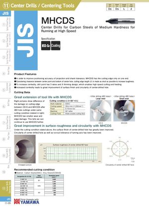
JIS MHCDS
Center Drills for Carbon Steels of Medium Hardness for
Running at High Speed
Specification
Coating
Product Features
●In order to improve positioning accuracy of projection and shank tolerance, MHCDS has the cutting edge only on one end.
- Considering clearance between center point and bottom of center hole, cutting edge length (ℓ) is made as short as possible to increase toughness.
●To increase centrality, drill point has 3 rakes and X thinning design, which enables high speed cutting and feeding. ●Increased centrality leads to great improvement of surface finish and circularity of center-drilled hole.
Cutting Data
| Great extension of tool life with MHCDS | <After drilling 480 holes> | <After drilling 480 holes> | |||
| Large wear | Small wear | ||||
| Right pictures show difference of | Cutting condition [ 3×60°×8 ] |
| the damage on cutting edge | Work material | S55C |
| between CD-S and MHCDS after | Cutting speed | 30m/min (1,200min-1) |
| Feed | 0.15mm/rev | |
| 480 hole cuttings under same | ||
| Machine | NC lathe | |
| cutting condition (stated in right) | Cutting Fluid | Water soluble cutting fluid |
MHCDS has smaller wear and edge damage. This tells we can continue to use MHCDS further. CD-S MHCDS
Great improvement in surface roughness and circularity with MHCDS
Under the cutting condition stated above, the surface finish of center-drilled hole has greatly been improved. Circularity of center drilled hole as well as run-out tolerance of turning axis has been improved. 90 135 45 μm Surface roughness of center drilled 60°face 180 0
225 315 100μm 270
0.5 1.0 1.5 2.0 mm ×100
Enlarged picture Circularity of center drilled 60°face Recommended cutting condition ●Material : Carbon Steels(S55C) Alloy Steels(SCM440)
| Designation Dc×θ×Ds | Feed (mm/rev) | Revolution speed (min-1) |
| 1×60゜×4 | 01 | 3,800 |
| 1.5×60゜×5 | . | 2,400 |
| 2×60゜×6 | 1,900 | |
| 2.5×60゜×8 | 0.15 | 1,500 |
| 3×60゜×8 | 1,200 | |
| 4×60゜×10 | 1,000 | |
| 5×60゜×12 | 0.2 | 800 |
| 6×60゜×16 | 600 |