Каталог Dormer Pramet фрезерование 2021 - 2022 - страница 781
Навигация
 Каталог оснастка Dormer Pramet 2016
 Каталог Dormer Pramet обработка резьбы 2021 - 2022
 Общий каталог Dormer Pramet 2016
 Общий каталог Dormer Pramet 2018
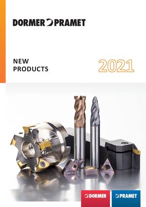 Брошюра Dormer Pramet новинки 2021
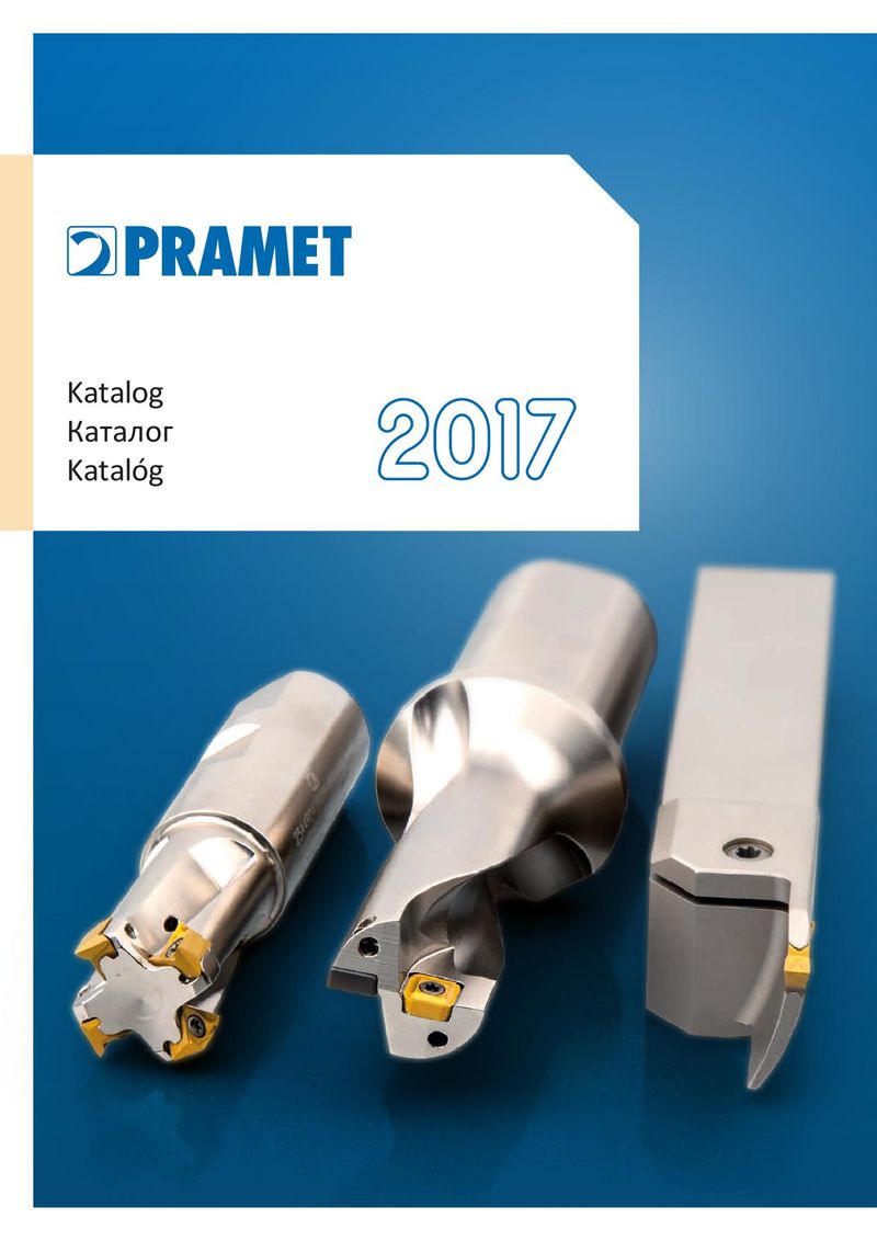 Общий каталог Dormer Pramet 2017
- MILLING – GENERAL CONTENT
- WORKPIECE MATERIAL GROUPS (WMG)
- CUTTING TOOL PARAMETERS ACCORDING TO ISO 13399
- SOLID HM & HSS MILLS
- CONTENT
- INSTRUCTIONS
- PAGE OVERVIEW
- ICONS OVERVIEW
- SOLID HM MILLS
- TOOL MATERIALS AND SURFACE COATINGS NAVIGATOR
- FAMILIES
- NAVIGATOR
- S2xx
- S216
- S217
- S218
- S219
- S225
- S226
- S227
- S229
- S231
- S233
- S260
- S262
- S264
- S5xx
- S501
- S511
- S521
- S523
- S524
- S525
- S526
- S527
- S529
- S531
- S533
- S534
- S535
- S536
- S561
- S6xx
- S610
- S611
- S612
- S614
- S629
- S637
- S638
- S650
- S654
- S662
- S7xx
- S710
- S713
- S714
- S715
- S716
- S717
- S718
- S722HB
- S739
- S740
- S761
- S763
- S765
- S765HB
- S766
- S767
- S768
- S770HB
- S771HB
- S772HB
- S773HB
- S791
- S8xx
- S802HA
- S802HB
- S803HA
- S803HB
- S804HA
- S804HB
- S812HA
- S812HB
- S813HA
- S813HB
- S814HA
- S814HB
- S822
- S823
- S9xx
- S902
- S903
- S904
- S922
- S933
- S944
- S991
- FEED PER TOOTH TABLE
- CORRECTION FACTORS
- BARREL-SHAPE MILL – FEED PER TOOTH TABLE
- SOLID HSS MILLS
- TOOL MATERIALS NAVIGATOR
- SURFACE TREATMENTS AND COATINGS NAVIGATOR
- NAVIGATOR
- C1xx
- C110
- C122
- C123
- C126
- C135
- C139
- C159
- C167
- C2xx
- C246
- C247
- C273
- C295
- C3xx
- C305
- C306
- C333
- C336
- C346
- C352
- C353
- C367
- C4xx
- C400
- C403
- C407
- C413
- C428
- C492
- C5xx
- C500
- C505
- C7xx
- C700
- C710
- C8xx
- C800
- C801
- C810
- C820
- C822
- C825
- C830
- C831
- C837
- C835
- C9xx
- C907
- C908
- C920
- C922
- C948
- Dxxx
- D200
- D400
- D402
- D420
- D422
- D745
- D747
- D750
- D751
- D753
- D752
- D763
- FEED PER TOOTH TABLE
- CORRECTION FACTORS
- SLITTING SAWS – TOOTH PITCH CHOICE TABLES
- TECHNICAL INFORMATION
- HSS MATERIALS
- HM MATERIALS
- SURFACE TREATMENTS / SURFACE COATINGS
- MILLING TECHNICAL INFO
- OPERATING FORMULAS
- TROUBLESHOOTING
- ROTARY BURRS
- CONTENT
- CARBIDE ROTARY BURRS
- PAGE OVERVIEW
- ICONS OVERVIEW
- TOOL MATERIALS NAVIGATOR
- SURFACE AND TREATMENTS COATINGS NAVIGATOR
- NAVIGATOR
- RECOMMENDED OPERATING SPEED (RPM)
- P1xx
- P100
- P101
- P5xx
- P501
- P505
- P507
- P509
- P511
- P513
- P515
- P521
- P523
- P6xx
- P601
- P605
- P607
- P609
- P611
- P613
- P615
- P621
- P7xx
- P701
- P703
- P705
- P707
- P709
- P711
- P713
- P715
- P721
- P8xx
- P801
- P801C
- P803
- P803C
- P805
- P805C
- P807
- P807C
- P809
- P811
- P811C
- P813
- P813C
- P815
- P815C
- P817
- P819
- P821
- P821C
- P823
- P825
- P831
- P833
- P835
- P837
- P841
- P842
- P843
- P844
- P880
- P890
- GENERAL HINTS
- THREAD MILLS
- CONTENT
- PAGE OVERVIEW
- ICONS OVERVIEW
- TOOL MATERIALS AND SURFACE COATINGS NAVIGATOR
- NAVIGATOR
- J200
- J205
- J210
- J215
- J220
- J225
- J235
- J245
- J260
- J280
- FEED PER TOOTH TABLE
- NUMBER OF PASSES TABLE
- GENERAL HINTS
- INDEXABLE MILLS
- CONTENT
- INSTRUCTIONS
- CUTTERS – PAGE OVERVIEW
- INSERTS – PAGE OVERVIEW
- ICONS OVERVIEW
- PROGRAM OVERVIEW
- GRADES – NAVIGATOR
- GRADES – OVERVIEW
- NAVIGATOR
- FACE MILLING
- SQUARE SHOULDER MILLING
- DEEP SHOULDER MILLING
- SLOT MILLING
- COPY MILLING
- HIGH FEED MILLING
- CHAMFER, T-SLOT MILLING
- ISO CODE DESIGNATION – SHELL MILL BODIES
- ISO CODE DESIGNATION – END SHOULDER MILL BODIES
- ISO CODE DESIGNATION – MILLING INSERTS
- FACE MILLS
- SHN06C
- SHN09C
- SOD05
- SOD06D
- SOE06Z
- SOE09Z
- SSE09
- SSN12Z
- SPN13
- CHN09
- FSB22X
- SQUARE SHOULDER MILLS
- SAD07D
- SAD11E
- SAD16E
- SAP10D
- SAP16D
- STN10
- STN16
- SLN12
- SLN16
- SSO05O
- SSO09
- SSD12
- FTB27X
- DEEP SHOULDER MILLS
- J(T)-SAD11E
- J(T)-SAD16E
- J(T)-SLSN
- J(T)-SSAP
- J(T)-2416
- J(T)-CSD12X
- SLOT MILLS
- S90SN
- S90CN(XN)
- COPY MILLS
- SRC10
- SRC12
- SRC16
- SRC20
- SRD05
- SRD07
- SRD10
- SRD12
- SRD16
- L2-SZP
- K3-CXP
- K2-SRC
- K2-SLC
- K2-PPH
- SVC22C
- SWN04C
- SCN05C
- HIGH FEED MILLS
- SBN10
- SSN11
- SPD09
- SZD07
- SZD09
- SZD12
- CHAMFER & T-SLOTS MILLS
- SSD09
- N-SSO09
- 2516
- 2636
- J(T)-SXP16
- F-SCC
- OTHER MILLING INSERTS
- ADKT 15
- ADKX 15
- APMT 16
- CNM
- ODMT 05
- OFKR 07
- RDET
- RDEX
- RDHX 20
- RPET 12
- RPEW 12
- RPEX
- SEEN
- SEER
- SEET 12
- SEET 12-FA
- SEET 12-PM
- SEEW 12
- SFCN
- SNHF
- SNHN
- SNKX
- SNUN
- SPGN
- SPGN 25 DZ
- SPKN
- SPKR
- SPKX
- SPUN
- TNJF
- TPCN 16
- TPKN
- TPKR
- TPUN
- VCGT 22-FA
- XDHW
- TECHNICAL INFORMATION
- WORKPIECE MATERIAL GROUP (WMG)
- CORRECTION FACTORS
- DEFINITION OF BASIC TERMS
- NOMOGRAM FOR CALCULATING THE WORKING GEOMETRY OF MILLING TOOLS
- CHOICE OF TOOL
- CHOICE OF CUTTING INSERT
- GEOMETRY OF MILLING INSERTS
- A
- ADEX 07-FA
- ADEX 11T308SR-HF ADEX 07-HF
- ADEX 11-FA
- ADEX 11-HF
- ADEX 11-HF2
- ADEX 16-FA
- ADEX 16-FM
- ADEX 16-HF
- ADEX 16-HF2
- ADKT 15-M
- ADKX 15-F
- ADKX 15-F (RAD)
- ADMX 07-F
- ADMX 07-M
- ADMX 11-F
- ADMX 11-M
- ADMX 11-MF
- ADMX 11-MM
- ADMX 11-R
- ADMX 16-F
- ADMX 160616PR-R ADMX 16-M
- ADMX 16-MF
- ADMX 16-MM
- ADMX 16-R
- ANHX 10-F
- APET 15EN
- APET 15SN
- APET 16-FA
- APEW 15ER
- APEW 15SR
- APKT 10-FA
- APKT 10-M
- APKT 16-GM
- APKT 16-HM
- ? APMT 1604PDER-FM APMT 16-F
- APMT 16-FM
- APMT 16 ER-R
- APMT 16 SR-R
- B
- BNGX 10-HM
- BNGX 10-M
- BNGX 10-MM
- C
- CCMX -TS1
- CNHQ 10
- CNHX 05-WM
- CNM 563
- H
- HNEF 09-F
- HNEF 09-M
- HNEF 09-W
- HNGX 06-F
- HNGX 06-M
- HNGX 06-R
- HNGX 09-F
- HNGX 09-FF
- HNGX 09-M
- HNGX 09-R
- HNMF 09-R
- L
- LC 12-CH
- LC 12-RE
- LC -KP
- LC -KPF
- LNET 16-M
- LNET 16-R
- LNG(U)X 12-M
- LNGU 16-FA
- LNGU 16-M
- LNGX 12-F
- LNGX 12-FA
- LNGX 12-MF
- LNGX 12-MM
- LNGX 12-R
- LNMU 16-F
- LNMU 16-M
- LNMU 16-R
- O
- ODEW 06
- ODKT 05-F
- ODK(M)T 05-FM
- ODMT 05-R
- ODMT 06
- ODMX 06
- OEHT 06-FA
- OEHT 06-M
- OEHT 06-MF
- OEHT 06-MM
- OEHT09-M
- OEHT 09-MM
- OFKR 07-M
- P
- PDKT 09-FM
- PDKX 09-FM
- PDMW 09
- ? PNMQ 1308DNSN PDMX 09-M
- PDMX 09-R
- PNMQ 13
- PNMU 13-M
- PPH -CL1
- PPH -CL4
- PPHE -SM1
- PPHF -CE1
- PPHT-A2
- R
- RC
- RC -F
- RCMT -F
- RCMT -M
- RCMT -R
- RCMT SN-R
- RCMT 12EN-R
- RDET
- RDEW
- RDEX 12
- RDEX 16
- RDGT 07
- RDGT 10
- RDGT 12
- RDGT 12-F
- RDGT 12-FM
- RDHT -FA
- RDHX 05
- RDHX MOT
- RDMT
- RDMT 12
- RDMT -R
- RDMX
- REHT -M
- REHT -MM
- RPET 12
- RPET 15-M
- RPEW 12
- RPEW 15
- RPEX -12
- S
- SBKX 22
- SBMR 22
- SBMR 22-R
- SDEW 09EN
- SDEW 09SN
- SDEX 09-74
- SDGX 12-FM
- SDKT 12-F (IM)
- SDMT 12-F
- SDMT 12-F (IM)
- SDK(M)T 12-FM (IM)
- SDMT 12-R (IM)
- SDMT 12-M
- SDMT 12-R
- SDMX 12-M
- SEEN 12FN
- SEEN SN
- SEER EN
- SEER SN
- SEET 09
- SEET 12EN
- SEET 12SN
- SEET 12-FA
- SEET 12-PM
- SEEW 12 EN
- SEEW 12 SN
- SEMT 09
- SFCN 12
- SNET 13-M
- SNGX 11-M
- SNGX 11-MM
- SNGX 13-M
- SNGX 13-R
- SNHF -M
- SNHN
- SNHQ 11
- SNHQ 12TN
- SNHQ 12EN
- SNHQ 12TRL
- SNK(M)T 12-M
- SNKX
- SNMT 12-R
- SNUN
- SOMT 05-M
- SOMT 09-M
- SOMT 09-MI
- SOMT 09-P
- SPET 12EN
- SPET 12S
- SPEW 12EN
- SPEW 12SN
- SPGN
- SPGN DZ
- SPKN EDSR(L)
- SPKN EDER(L)
- SPKR
- SPKX
- SPUN
- SPUN 25
- T
- TBMR 27
- TCMT 16-FM
- TNGX 10-F
- TNGX 10-FA
- TNGX 10-M
- TNGX 16-F
- TNGX 16-FA
- TNGX 16-M
- TNJF 12
- TPCN 16
- TPKN ER
- TPKN SR
- TPKR
- TPUN
- V
- VCGT 22-FA
- W
- WNHX 04-WM
- X
- XDHW EN
- XDHW SN
- XEHT
- XNGX ANSN
- XNGX 13
- XNHQ TN
- XP ER-FM
- XPHT 16E
- XPHT 16-FA
- XPHT 16S
- Z
- ZDCW 07
- ZDCW 09
- ZDEW 12
- ZP ER-F
- ZP ER-FM
- ZP ER-M
- ZP ER-R
- MILLING GRADES – OVERVIEW
- WORKING CONDITION WHEN MILLING
- MACHINED SURFACE ROUGHNESS
- TECHNOLOGIES
- TYPES OF WEAR ON MILLING INSERTS
- FORMULAS
- RECOMMENDED TORQUE OF CLAMPING SCREWS
- TECHNICAL INFORMATION ON INSERT BOX
- HARDNESS CONVERSION TABLE

INSERT FRACTURE
↓ (H) grain has a great influence. (MT)CVD + PVD coating recommended. PVD
f ↓
Very important to reduce cutting force.
v ↑↓
It is about swarf control and vibration.
| ap | ↓ | Reduces the force load. |
| ↓ | Use less positive cutting geometry. | |
| It has no influence. | ||
| Use better working conditions (ae/DC). |
POOR SURFACE QUALITY
Description and cause: Corrective measures: Numerous causes depending on the workpiece material, cutting Use a finishing insert, or an insert with finishing segment conditons (feed rate and cutting speed), the condition of the cutting Use an insert with suitable cutting geometry edge, the extent and type of wear, and the condition and rigidity of the
- Reduce the feed rate
machine – tool – workpiece assembly.
- Adjust (usually increase) the cutting speed
- Incorrect tool chosen
- Use coolant or lubrication (MQL)
- Incorrect chip thickness
- Eliminate vibrations
- Incorrect cutting speed
- Use a tool with which the position of the individual inserts can be
- Coolant is needed
adjusted more accurately
- High feed rate
- Change the chip thickness (modify the machining conditions)
VIBRATIONS
| Description and cause: | Corrective measures: |
| This is a very common problem, which is mainly caused by an | • Check the stability of the workpiece fixing |
| unbalanced workpiece or tool, unstable fixing of the machined part and | • Check the stability of the tool fixing |
high cutting forces.
- Reduce the cutting depth
- Low rigidity of machine-tool-workpiece assembly
- Use a tool with smaller overhang
- Excessive chip depth (both axial and radial)
- Modify the cutting speed
- Run-out – poor workpiece or tool balance
- Reduce the chip thickness
- Large tool overhang (change the cutting or machining conditions)
- Choose a suitable cutting geometry and tool material to minimize the cutting process force balance (as sharp and as positive as possible), i.e. use a tool with a lower cutting resistance
- When milling, use a tool with a smaller setting angle