Каталог Dormer Pramet фрезерование 2021 - 2022 - страница 772
Навигация
 Каталог оснастка Dormer Pramet 2016
 Каталог Dormer Pramet обработка резьбы 2021 - 2022
 Общий каталог Dormer Pramet 2016
 Общий каталог Dormer Pramet 2018
 Брошюра Dormer Pramet новинки 2021
 Общий каталог Dormer Pramet 2017
- MILLING – GENERAL CONTENT
- WORKPIECE MATERIAL GROUPS (WMG)
- CUTTING TOOL PARAMETERS ACCORDING TO ISO 13399
- SOLID HM & HSS MILLS
- CONTENT
- INSTRUCTIONS
- PAGE OVERVIEW
- ICONS OVERVIEW
- SOLID HM MILLS
- TOOL MATERIALS AND SURFACE COATINGS NAVIGATOR
- FAMILIES
- NAVIGATOR
- S2xx
- S216
- S217
- S218
- S219
- S225
- S226
- S227
- S229
- S231
- S233
- S260
- S262
- S264
- S5xx
- S501
- S511
- S521
- S523
- S524
- S525
- S526
- S527
- S529
- S531
- S533
- S534
- S535
- S536
- S561
- S6xx
- S610
- S611
- S612
- S614
- S629
- S637
- S638
- S650
- S654
- S662
- S7xx
- S710
- S713
- S714
- S715
- S716
- S717
- S718
- S722HB
- S739
- S740
- S761
- S763
- S765
- S765HB
- S766
- S767
- S768
- S770HB
- S771HB
- S772HB
- S773HB
- S791
- S8xx
- S802HA
- S802HB
- S803HA
- S803HB
- S804HA
- S804HB
- S812HA
- S812HB
- S813HA
- S813HB
- S814HA
- S814HB
- S822
- S823
- S9xx
- S902
- S903
- S904
- S922
- S933
- S944
- S991
- FEED PER TOOTH TABLE
- CORRECTION FACTORS
- BARREL-SHAPE MILL – FEED PER TOOTH TABLE
- SOLID HSS MILLS
- TOOL MATERIALS NAVIGATOR
- SURFACE TREATMENTS AND COATINGS NAVIGATOR
- NAVIGATOR
- C1xx
- C110
- C122
- C123
- C126
- C135
- C139
- C159
- C167
- C2xx
- C246
- C247
- C273
- C295
- C3xx
- C305
- C306
- C333
- C336
- C346
- C352
- C353
- C367
- C4xx
- C400
- C403
- C407
- C413
- C428
- C492
- C5xx
- C500
- C505
- C7xx
- C700
- C710
- C8xx
- C800
- C801
- C810
- C820
- C822
- C825
- C830
- C831
- C837
- C835
- C9xx
- C907
- C908
- C920
- C922
- C948
- Dxxx
- D200
- D400
- D402
- D420
- D422
- D745
- D747
- D750
- D751
- D753
- D752
- D763
- FEED PER TOOTH TABLE
- CORRECTION FACTORS
- SLITTING SAWS – TOOTH PITCH CHOICE TABLES
- TECHNICAL INFORMATION
- HSS MATERIALS
- HM MATERIALS
- SURFACE TREATMENTS / SURFACE COATINGS
- MILLING TECHNICAL INFO
- OPERATING FORMULAS
- TROUBLESHOOTING
- ROTARY BURRS
- CONTENT
- CARBIDE ROTARY BURRS
- PAGE OVERVIEW
- ICONS OVERVIEW
- TOOL MATERIALS NAVIGATOR
- SURFACE AND TREATMENTS COATINGS NAVIGATOR
- NAVIGATOR
- RECOMMENDED OPERATING SPEED (RPM)
- P1xx
- P100
- P101
- P5xx
- P501
- P505
- P507
- P509
- P511
- P513
- P515
- P521
- P523
- P6xx
- P601
- P605
- P607
- P609
- P611
- P613
- P615
- P621
- P7xx
- P701
- P703
- P705
- P707
- P709
- P711
- P713
- P715
- P721
- P8xx
- P801
- P801C
- P803
- P803C
- P805
- P805C
- P807
- P807C
- P809
- P811
- P811C
- P813
- P813C
- P815
- P815C
- P817
- P819
- P821
- P821C
- P823
- P825
- P831
- P833
- P835
- P837
- P841
- P842
- P843
- P844
- P880
- P890
- GENERAL HINTS
- THREAD MILLS
- CONTENT
- PAGE OVERVIEW
- ICONS OVERVIEW
- TOOL MATERIALS AND SURFACE COATINGS NAVIGATOR
- NAVIGATOR
- J200
- J205
- J210
- J215
- J220
- J225
- J235
- J245
- J260
- J280
- FEED PER TOOTH TABLE
- NUMBER OF PASSES TABLE
- GENERAL HINTS
- INDEXABLE MILLS
- CONTENT
- INSTRUCTIONS
- CUTTERS – PAGE OVERVIEW
- INSERTS – PAGE OVERVIEW
- ICONS OVERVIEW
- PROGRAM OVERVIEW
- GRADES – NAVIGATOR
- GRADES – OVERVIEW
- NAVIGATOR
- FACE MILLING
- SQUARE SHOULDER MILLING
- DEEP SHOULDER MILLING
- SLOT MILLING
- COPY MILLING
- HIGH FEED MILLING
- CHAMFER, T-SLOT MILLING
- ISO CODE DESIGNATION – SHELL MILL BODIES
- ISO CODE DESIGNATION – END SHOULDER MILL BODIES
- ISO CODE DESIGNATION – MILLING INSERTS
- FACE MILLS
- SHN06C
- SHN09C
- SOD05
- SOD06D
- SOE06Z
- SOE09Z
- SSE09
- SSN12Z
- SPN13
- CHN09
- FSB22X
- SQUARE SHOULDER MILLS
- SAD07D
- SAD11E
- SAD16E
- SAP10D
- SAP16D
- STN10
- STN16
- SLN12
- SLN16
- SSO05O
- SSO09
- SSD12
- FTB27X
- DEEP SHOULDER MILLS
- J(T)-SAD11E
- J(T)-SAD16E
- J(T)-SLSN
- J(T)-SSAP
- J(T)-2416
- J(T)-CSD12X
- SLOT MILLS
- S90SN
- S90CN(XN)
- COPY MILLS
- SRC10
- SRC12
- SRC16
- SRC20
- SRD05
- SRD07
- SRD10
- SRD12
- SRD16
- L2-SZP
- K3-CXP
- K2-SRC
- K2-SLC
- K2-PPH
- SVC22C
- SWN04C
- SCN05C
- HIGH FEED MILLS
- SBN10
- SSN11
- SPD09
- SZD07
- SZD09
- SZD12
- CHAMFER & T-SLOTS MILLS
- SSD09
- N-SSO09
- 2516
- 2636
- J(T)-SXP16
- F-SCC
- OTHER MILLING INSERTS
- ADKT 15
- ADKX 15
- APMT 16
- CNM
- ODMT 05
- OFKR 07
- RDET
- RDEX
- RDHX 20
- RPET 12
- RPEW 12
- RPEX
- SEEN
- SEER
- SEET 12
- SEET 12-FA
- SEET 12-PM
- SEEW 12
- SFCN
- SNHF
- SNHN
- SNKX
- SNUN
- SPGN
- SPGN 25 DZ
- SPKN
- SPKR
- SPKX
- SPUN
- TNJF
- TPCN 16
- TPKN
- TPKR
- TPUN
- VCGT 22-FA
- XDHW
- TECHNICAL INFORMATION
- WORKPIECE MATERIAL GROUP (WMG)
- CORRECTION FACTORS
- DEFINITION OF BASIC TERMS
- NOMOGRAM FOR CALCULATING THE WORKING GEOMETRY OF MILLING TOOLS
- CHOICE OF TOOL
- CHOICE OF CUTTING INSERT
- GEOMETRY OF MILLING INSERTS
- A
- ADEX 07-FA
- ADEX 11T308SR-HF ADEX 07-HF
- ADEX 11-FA
- ADEX 11-HF
- ADEX 11-HF2
- ADEX 16-FA
- ADEX 16-FM
- ADEX 16-HF
- ADEX 16-HF2
- ADKT 15-M
- ADKX 15-F
- ADKX 15-F (RAD)
- ADMX 07-F
- ADMX 07-M
- ADMX 11-F
- ADMX 11-M
- ADMX 11-MF
- ADMX 11-MM
- ADMX 11-R
- ADMX 16-F
- ADMX 160616PR-R ADMX 16-M
- ADMX 16-MF
- ADMX 16-MM
- ADMX 16-R
- ANHX 10-F
- APET 15EN
- APET 15SN
- APET 16-FA
- APEW 15ER
- APEW 15SR
- APKT 10-FA
- APKT 10-M
- APKT 16-GM
- APKT 16-HM
- ? APMT 1604PDER-FM APMT 16-F
- APMT 16-FM
- APMT 16 ER-R
- APMT 16 SR-R
- B
- BNGX 10-HM
- BNGX 10-M
- BNGX 10-MM
- C
- CCMX -TS1
- CNHQ 10
- CNHX 05-WM
- CNM 563
- H
- HNEF 09-F
- HNEF 09-M
- HNEF 09-W
- HNGX 06-F
- HNGX 06-M
- HNGX 06-R
- HNGX 09-F
- HNGX 09-FF
- HNGX 09-M
- HNGX 09-R
- HNMF 09-R
- L
- LC 12-CH
- LC 12-RE
- LC -KP
- LC -KPF
- LNET 16-M
- LNET 16-R
- LNG(U)X 12-M
- LNGU 16-FA
- LNGU 16-M
- LNGX 12-F
- LNGX 12-FA
- LNGX 12-MF
- LNGX 12-MM
- LNGX 12-R
- LNMU 16-F
- LNMU 16-M
- LNMU 16-R
- O
- ODEW 06
- ODKT 05-F
- ODK(M)T 05-FM
- ODMT 05-R
- ODMT 06
- ODMX 06
- OEHT 06-FA
- OEHT 06-M
- OEHT 06-MF
- OEHT 06-MM
- OEHT09-M
- OEHT 09-MM
- OFKR 07-M
- P
- PDKT 09-FM
- PDKX 09-FM
- PDMW 09
- ? PNMQ 1308DNSN PDMX 09-M
- PDMX 09-R
- PNMQ 13
- PNMU 13-M
- PPH -CL1
- PPH -CL4
- PPHE -SM1
- PPHF -CE1
- PPHT-A2
- R
- RC
- RC -F
- RCMT -F
- RCMT -M
- RCMT -R
- RCMT SN-R
- RCMT 12EN-R
- RDET
- RDEW
- RDEX 12
- RDEX 16
- RDGT 07
- RDGT 10
- RDGT 12
- RDGT 12-F
- RDGT 12-FM
- RDHT -FA
- RDHX 05
- RDHX MOT
- RDMT
- RDMT 12
- RDMT -R
- RDMX
- REHT -M
- REHT -MM
- RPET 12
- RPET 15-M
- RPEW 12
- RPEW 15
- RPEX -12
- S
- SBKX 22
- SBMR 22
- SBMR 22-R
- SDEW 09EN
- SDEW 09SN
- SDEX 09-74
- SDGX 12-FM
- SDKT 12-F (IM)
- SDMT 12-F
- SDMT 12-F (IM)
- SDK(M)T 12-FM (IM)
- SDMT 12-R (IM)
- SDMT 12-M
- SDMT 12-R
- SDMX 12-M
- SEEN 12FN
- SEEN SN
- SEER EN
- SEER SN
- SEET 09
- SEET 12EN
- SEET 12SN
- SEET 12-FA
- SEET 12-PM
- SEEW 12 EN
- SEEW 12 SN
- SEMT 09
- SFCN 12
- SNET 13-M
- SNGX 11-M
- SNGX 11-MM
- SNGX 13-M
- SNGX 13-R
- SNHF -M
- SNHN
- SNHQ 11
- SNHQ 12TN
- SNHQ 12EN
- SNHQ 12TRL
- SNK(M)T 12-M
- SNKX
- SNMT 12-R
- SNUN
- SOMT 05-M
- SOMT 09-M
- SOMT 09-MI
- SOMT 09-P
- SPET 12EN
- SPET 12S
- SPEW 12EN
- SPEW 12SN
- SPGN
- SPGN DZ
- SPKN EDSR(L)
- SPKN EDER(L)
- SPKR
- SPKX
- SPUN
- SPUN 25
- T
- TBMR 27
- TCMT 16-FM
- TNGX 10-F
- TNGX 10-FA
- TNGX 10-M
- TNGX 16-F
- TNGX 16-FA
- TNGX 16-M
- TNJF 12
- TPCN 16
- TPKN ER
- TPKN SR
- TPKR
- TPUN
- V
- VCGT 22-FA
- W
- WNHX 04-WM
- X
- XDHW EN
- XDHW SN
- XEHT
- XNGX ANSN
- XNGX 13
- XNHQ TN
- XP ER-FM
- XPHT 16E
- XPHT 16-FA
- XPHT 16S
- Z
- ZDCW 07
- ZDCW 09
- ZDEW 12
- ZP ER-F
- ZP ER-FM
- ZP ER-M
- ZP ER-R
- MILLING GRADES – OVERVIEW
- WORKING CONDITION WHEN MILLING
- MACHINED SURFACE ROUGHNESS
- TECHNOLOGIES
- TYPES OF WEAR ON MILLING INSERTS
- FORMULAS
- RECOMMENDED TORQUE OF CLAMPING SCREWS
- TECHNICAL INFORMATION ON INSERT BOX
- HARDNESS CONVERSION TABLE
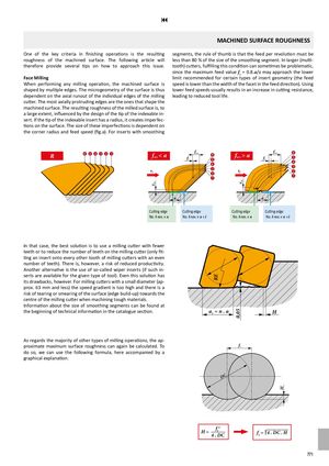
axy RE axy0,05 H 9 MACHINED SURFACE ROUGHNESS One of the key criteria in finishing operations is the resulting segments, the rule of thumb is that the feed per revolution must be roughness of the machined surface. The following article will less than 80 % of the size of the smoothing segment. In larger (multi- therefore provide several tips on how to approach this issue. tooth) cutters, fulfilling this condition can sometimes be problematic, since the maximum feed value fz = 0.8.a/z may approach the lower Face Milling limit recommended for certain types of insert geometry (the feed When performing any milling operation, the machined surface is speed is lower than the width of the facet in the feed direction). Using shaped by multiple edges. The microgeometry of the surface is thus lower feed speeds usually results in an increase in cutting resistance, dependent on the axial runout of the individual edges of the milling leading to reduced tool life. cutter. The most axially protruding edges are the ones that shape the machined surface. The resulting roughness of the milled surface is, to a large extent, influenced by the design of the tip of the indexable in- sert. If the tip of the indexable insert has a radius, it creates imperfec- tions on the surface. The size of these imperfections is dependent on the corner radius and feed speed (fig.a). For inserts with smoothing R 6 5 4 3 2 1 frev < a frev 6fz5 frev > a frevfz 65 4 4 3 vf 3 vf 2 2 1 1 a a Cutting edge Cutting edge Cutting edge Cutting edge No. 4 rev. × n No. 4 rev. × n +1 No. 4 rev. × n No. 4 rev. × n +1 In that case, the best solution is to use a milling cutter with fewer teeth or to reduce the number of teeth on the milling cutter (only fit- ting an insert onto every other tooth of milling cutters with an even number of teeth). There is, however, a risk of reduced productivity. Another alternative is the use of so-called wiper inserts (if such in- serts are available for the given type of tool). Even this solution has its drawbacks, however. For milling cutters with a small diameter (ap- prox. 63 mm and less) the speed gradient is too high and there is a risk of tearing or smearing of the surface (edge build-up) towards the centre of the milling cutter when machining tough materials. Information about the size of smoothing segments can be found at the beginning of technical information in the catalogue section. a1 = n . a H As regards the majority of other types of milling operations, the ap- proximate maximum surface roughness can again be calculated. To fe do so, we can use the following formula, here accompanied by a graphical explanation. DC H= fe24 . DC fe = 4 . DC . H 771