Каталог Dormer Pramet фрезерование 2021 - 2022 - страница 770
Навигация
 Каталог оснастка Dormer Pramet 2016
 Каталог Dormer Pramet обработка резьбы 2021 - 2022
 Общий каталог Dormer Pramet 2016
 Общий каталог Dormer Pramet 2018
 Брошюра Dormer Pramet новинки 2021
 Общий каталог Dormer Pramet 2017
- MILLING – GENERAL CONTENT
- WORKPIECE MATERIAL GROUPS (WMG)
- CUTTING TOOL PARAMETERS ACCORDING TO ISO 13399
- SOLID HM & HSS MILLS
- CONTENT
- INSTRUCTIONS
- PAGE OVERVIEW
- ICONS OVERVIEW
- SOLID HM MILLS
- TOOL MATERIALS AND SURFACE COATINGS NAVIGATOR
- FAMILIES
- NAVIGATOR
- S2xx
- S216
- S217
- S218
- S219
- S225
- S226
- S227
- S229
- S231
- S233
- S260
- S262
- S264
- S5xx
- S501
- S511
- S521
- S523
- S524
- S525
- S526
- S527
- S529
- S531
- S533
- S534
- S535
- S536
- S561
- S6xx
- S610
- S611
- S612
- S614
- S629
- S637
- S638
- S650
- S654
- S662
- S7xx
- S710
- S713
- S714
- S715
- S716
- S717
- S718
- S722HB
- S739
- S740
- S761
- S763
- S765
- S765HB
- S766
- S767
- S768
- S770HB
- S771HB
- S772HB
- S773HB
- S791
- S8xx
- S802HA
- S802HB
- S803HA
- S803HB
- S804HA
- S804HB
- S812HA
- S812HB
- S813HA
- S813HB
- S814HA
- S814HB
- S822
- S823
- S9xx
- S902
- S903
- S904
- S922
- S933
- S944
- S991
- FEED PER TOOTH TABLE
- CORRECTION FACTORS
- BARREL-SHAPE MILL – FEED PER TOOTH TABLE
- SOLID HSS MILLS
- TOOL MATERIALS NAVIGATOR
- SURFACE TREATMENTS AND COATINGS NAVIGATOR
- NAVIGATOR
- C1xx
- C110
- C122
- C123
- C126
- C135
- C139
- C159
- C167
- C2xx
- C246
- C247
- C273
- C295
- C3xx
- C305
- C306
- C333
- C336
- C346
- C352
- C353
- C367
- C4xx
- C400
- C403
- C407
- C413
- C428
- C492
- C5xx
- C500
- C505
- C7xx
- C700
- C710
- C8xx
- C800
- C801
- C810
- C820
- C822
- C825
- C830
- C831
- C837
- C835
- C9xx
- C907
- C908
- C920
- C922
- C948
- Dxxx
- D200
- D400
- D402
- D420
- D422
- D745
- D747
- D750
- D751
- D753
- D752
- D763
- FEED PER TOOTH TABLE
- CORRECTION FACTORS
- SLITTING SAWS – TOOTH PITCH CHOICE TABLES
- TECHNICAL INFORMATION
- HSS MATERIALS
- HM MATERIALS
- SURFACE TREATMENTS / SURFACE COATINGS
- MILLING TECHNICAL INFO
- OPERATING FORMULAS
- TROUBLESHOOTING
- ROTARY BURRS
- CONTENT
- CARBIDE ROTARY BURRS
- PAGE OVERVIEW
- ICONS OVERVIEW
- TOOL MATERIALS NAVIGATOR
- SURFACE AND TREATMENTS COATINGS NAVIGATOR
- NAVIGATOR
- RECOMMENDED OPERATING SPEED (RPM)
- P1xx
- P100
- P101
- P5xx
- P501
- P505
- P507
- P509
- P511
- P513
- P515
- P521
- P523
- P6xx
- P601
- P605
- P607
- P609
- P611
- P613
- P615
- P621
- P7xx
- P701
- P703
- P705
- P707
- P709
- P711
- P713
- P715
- P721
- P8xx
- P801
- P801C
- P803
- P803C
- P805
- P805C
- P807
- P807C
- P809
- P811
- P811C
- P813
- P813C
- P815
- P815C
- P817
- P819
- P821
- P821C
- P823
- P825
- P831
- P833
- P835
- P837
- P841
- P842
- P843
- P844
- P880
- P890
- GENERAL HINTS
- THREAD MILLS
- CONTENT
- PAGE OVERVIEW
- ICONS OVERVIEW
- TOOL MATERIALS AND SURFACE COATINGS NAVIGATOR
- NAVIGATOR
- J200
- J205
- J210
- J215
- J220
- J225
- J235
- J245
- J260
- J280
- FEED PER TOOTH TABLE
- NUMBER OF PASSES TABLE
- GENERAL HINTS
- INDEXABLE MILLS
- CONTENT
- INSTRUCTIONS
- CUTTERS – PAGE OVERVIEW
- INSERTS – PAGE OVERVIEW
- ICONS OVERVIEW
- PROGRAM OVERVIEW
- GRADES – NAVIGATOR
- GRADES – OVERVIEW
- NAVIGATOR
- FACE MILLING
- SQUARE SHOULDER MILLING
- DEEP SHOULDER MILLING
- SLOT MILLING
- COPY MILLING
- HIGH FEED MILLING
- CHAMFER, T-SLOT MILLING
- ISO CODE DESIGNATION – SHELL MILL BODIES
- ISO CODE DESIGNATION – END SHOULDER MILL BODIES
- ISO CODE DESIGNATION – MILLING INSERTS
- FACE MILLS
- SHN06C
- SHN09C
- SOD05
- SOD06D
- SOE06Z
- SOE09Z
- SSE09
- SSN12Z
- SPN13
- CHN09
- FSB22X
- SQUARE SHOULDER MILLS
- SAD07D
- SAD11E
- SAD16E
- SAP10D
- SAP16D
- STN10
- STN16
- SLN12
- SLN16
- SSO05O
- SSO09
- SSD12
- FTB27X
- DEEP SHOULDER MILLS
- J(T)-SAD11E
- J(T)-SAD16E
- J(T)-SLSN
- J(T)-SSAP
- J(T)-2416
- J(T)-CSD12X
- SLOT MILLS
- S90SN
- S90CN(XN)
- COPY MILLS
- SRC10
- SRC12
- SRC16
- SRC20
- SRD05
- SRD07
- SRD10
- SRD12
- SRD16
- L2-SZP
- K3-CXP
- K2-SRC
- K2-SLC
- K2-PPH
- SVC22C
- SWN04C
- SCN05C
- HIGH FEED MILLS
- SBN10
- SSN11
- SPD09
- SZD07
- SZD09
- SZD12
- CHAMFER & T-SLOTS MILLS
- SSD09
- N-SSO09
- 2516
- 2636
- J(T)-SXP16
- F-SCC
- OTHER MILLING INSERTS
- ADKT 15
- ADKX 15
- APMT 16
- CNM
- ODMT 05
- OFKR 07
- RDET
- RDEX
- RDHX 20
- RPET 12
- RPEW 12
- RPEX
- SEEN
- SEER
- SEET 12
- SEET 12-FA
- SEET 12-PM
- SEEW 12
- SFCN
- SNHF
- SNHN
- SNKX
- SNUN
- SPGN
- SPGN 25 DZ
- SPKN
- SPKR
- SPKX
- SPUN
- TNJF
- TPCN 16
- TPKN
- TPKR
- TPUN
- VCGT 22-FA
- XDHW
- TECHNICAL INFORMATION
- WORKPIECE MATERIAL GROUP (WMG)
- CORRECTION FACTORS
- DEFINITION OF BASIC TERMS
- NOMOGRAM FOR CALCULATING THE WORKING GEOMETRY OF MILLING TOOLS
- CHOICE OF TOOL
- CHOICE OF CUTTING INSERT
- GEOMETRY OF MILLING INSERTS
- A
- ADEX 07-FA
- ADEX 11T308SR-HF ADEX 07-HF
- ADEX 11-FA
- ADEX 11-HF
- ADEX 11-HF2
- ADEX 16-FA
- ADEX 16-FM
- ADEX 16-HF
- ADEX 16-HF2
- ADKT 15-M
- ADKX 15-F
- ADKX 15-F (RAD)
- ADMX 07-F
- ADMX 07-M
- ADMX 11-F
- ADMX 11-M
- ADMX 11-MF
- ADMX 11-MM
- ADMX 11-R
- ADMX 16-F
- ADMX 160616PR-R ADMX 16-M
- ADMX 16-MF
- ADMX 16-MM
- ADMX 16-R
- ANHX 10-F
- APET 15EN
- APET 15SN
- APET 16-FA
- APEW 15ER
- APEW 15SR
- APKT 10-FA
- APKT 10-M
- APKT 16-GM
- APKT 16-HM
- ? APMT 1604PDER-FM APMT 16-F
- APMT 16-FM
- APMT 16 ER-R
- APMT 16 SR-R
- B
- BNGX 10-HM
- BNGX 10-M
- BNGX 10-MM
- C
- CCMX -TS1
- CNHQ 10
- CNHX 05-WM
- CNM 563
- H
- HNEF 09-F
- HNEF 09-M
- HNEF 09-W
- HNGX 06-F
- HNGX 06-M
- HNGX 06-R
- HNGX 09-F
- HNGX 09-FF
- HNGX 09-M
- HNGX 09-R
- HNMF 09-R
- L
- LC 12-CH
- LC 12-RE
- LC -KP
- LC -KPF
- LNET 16-M
- LNET 16-R
- LNG(U)X 12-M
- LNGU 16-FA
- LNGU 16-M
- LNGX 12-F
- LNGX 12-FA
- LNGX 12-MF
- LNGX 12-MM
- LNGX 12-R
- LNMU 16-F
- LNMU 16-M
- LNMU 16-R
- O
- ODEW 06
- ODKT 05-F
- ODK(M)T 05-FM
- ODMT 05-R
- ODMT 06
- ODMX 06
- OEHT 06-FA
- OEHT 06-M
- OEHT 06-MF
- OEHT 06-MM
- OEHT09-M
- OEHT 09-MM
- OFKR 07-M
- P
- PDKT 09-FM
- PDKX 09-FM
- PDMW 09
- ? PNMQ 1308DNSN PDMX 09-M
- PDMX 09-R
- PNMQ 13
- PNMU 13-M
- PPH -CL1
- PPH -CL4
- PPHE -SM1
- PPHF -CE1
- PPHT-A2
- R
- RC
- RC -F
- RCMT -F
- RCMT -M
- RCMT -R
- RCMT SN-R
- RCMT 12EN-R
- RDET
- RDEW
- RDEX 12
- RDEX 16
- RDGT 07
- RDGT 10
- RDGT 12
- RDGT 12-F
- RDGT 12-FM
- RDHT -FA
- RDHX 05
- RDHX MOT
- RDMT
- RDMT 12
- RDMT -R
- RDMX
- REHT -M
- REHT -MM
- RPET 12
- RPET 15-M
- RPEW 12
- RPEW 15
- RPEX -12
- S
- SBKX 22
- SBMR 22
- SBMR 22-R
- SDEW 09EN
- SDEW 09SN
- SDEX 09-74
- SDGX 12-FM
- SDKT 12-F (IM)
- SDMT 12-F
- SDMT 12-F (IM)
- SDK(M)T 12-FM (IM)
- SDMT 12-R (IM)
- SDMT 12-M
- SDMT 12-R
- SDMX 12-M
- SEEN 12FN
- SEEN SN
- SEER EN
- SEER SN
- SEET 09
- SEET 12EN
- SEET 12SN
- SEET 12-FA
- SEET 12-PM
- SEEW 12 EN
- SEEW 12 SN
- SEMT 09
- SFCN 12
- SNET 13-M
- SNGX 11-M
- SNGX 11-MM
- SNGX 13-M
- SNGX 13-R
- SNHF -M
- SNHN
- SNHQ 11
- SNHQ 12TN
- SNHQ 12EN
- SNHQ 12TRL
- SNK(M)T 12-M
- SNKX
- SNMT 12-R
- SNUN
- SOMT 05-M
- SOMT 09-M
- SOMT 09-MI
- SOMT 09-P
- SPET 12EN
- SPET 12S
- SPEW 12EN
- SPEW 12SN
- SPGN
- SPGN DZ
- SPKN EDSR(L)
- SPKN EDER(L)
- SPKR
- SPKX
- SPUN
- SPUN 25
- T
- TBMR 27
- TCMT 16-FM
- TNGX 10-F
- TNGX 10-FA
- TNGX 10-M
- TNGX 16-F
- TNGX 16-FA
- TNGX 16-M
- TNJF 12
- TPCN 16
- TPKN ER
- TPKN SR
- TPKR
- TPUN
- V
- VCGT 22-FA
- W
- WNHX 04-WM
- X
- XDHW EN
- XDHW SN
- XEHT
- XNGX ANSN
- XNGX 13
- XNHQ TN
- XP ER-FM
- XPHT 16E
- XPHT 16-FA
- XPHT 16S
- Z
- ZDCW 07
- ZDCW 09
- ZDEW 12
- ZP ER-F
- ZP ER-FM
- ZP ER-M
- ZP ER-R
- MILLING GRADES – OVERVIEW
- WORKING CONDITION WHEN MILLING
- MACHINED SURFACE ROUGHNESS
- TECHNOLOGIES
- TYPES OF WEAR ON MILLING INSERTS
- FORMULAS
- RECOMMENDED TORQUE OF CLAMPING SCREWS
- TECHNICAL INFORMATION ON INSERT BOX
- HARDNESS CONVERSION TABLE
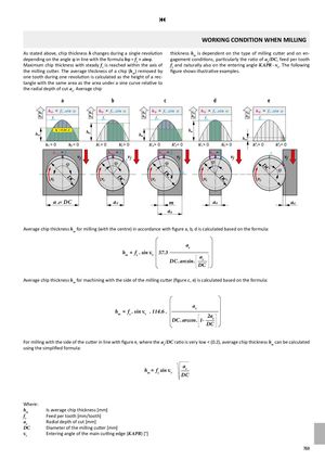
9 WORKING CONDITION WHEN MILLING As stated above, chip thickness h changes during a single revolution thickness hm is dependent on the type of milling cutter and on en- depending on the angle j in line with the formula hj = fz × sinj. gagement conditions, particularly the ratio of ae/DC, feed per tooth Maximum chip thickness with steady fz is reached within the axis of fz and naturally also on the entering angle KAPR – kr. The following the milling cutter. The average thickness of a chip (hm) removed by figure shows illustrative examples. one tooth during one revolution is calculated as the height of a rec- tangle with the same area as the area under a sine curve relative to the radial depth of cut ae. Average chip a b c d e hj hj = fz .sin j hj hj = fz .sin j hj hj = fz .sin j hj hj = fz .sin j hj hj = fz .sin j hm fz hm fz hm fz hm fz hm fz hm hm = 0,64 . fz hm hmhm hm h1 = 0 h2 = 0 h'1 > 0 h'2> 0 h'‚1> 0 h''2= 0 h'1 > 0 h'2> 0 h''1> 0 h''2= 0 hmax = fz hmax = fz hmax = fzvff vfvfjjj hm a x= fz f vf fz vfjDC vc DC vc DC DC fvc vc DC jvc a e= DC ae m ae ae ae Average chip thickness hm for milling (with the centre) in accordance with figure a, b, d is calculated based on the formula: ae hm = fz . sin k r 57.3 DC . arcsin . aeDC Average chip thickness hm for machining with the side of the milling cutter (figure c, e) is calculated based on the formula: hm = fz . sin kr . 114.6 . aeDC . arccos . 1-2ae DC For milling with the side of the cutter in line with figure e, where the ae/DC ratio is very low < (0.2), average chip thickness hm can be calculated using the simplified formula: hm = fz sin kr aeDC Where: hm Is average chip thickness [mm] fz Feed per tooth [mm/tooth] ae Radial depth of cut [mm] DC Diameter of the milling cutter [mm] kr Entering angle of the main cutting edge (KAPR) [°] 769