Основной каталог Kyocera 2021 - 2022 - страница 33
Навигация
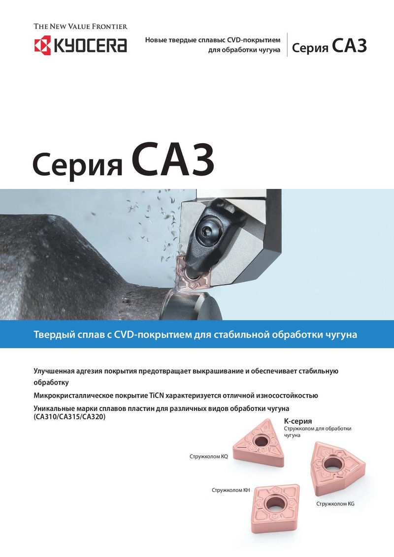 Каталог Kyocera пластины с CVD покрытием для обработки чугуна
 Каталог Kyocera пластины TQ для нарезания резьбы c прессованным стружколомом
 Каталог Kyocera высокопроизводительные модульные сверла DRA
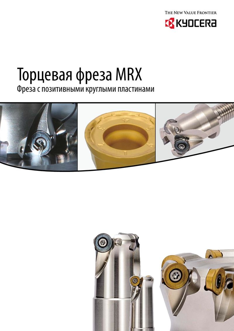 Каталог Kyocera фрезы MRX с позитивными круглыми пластинами
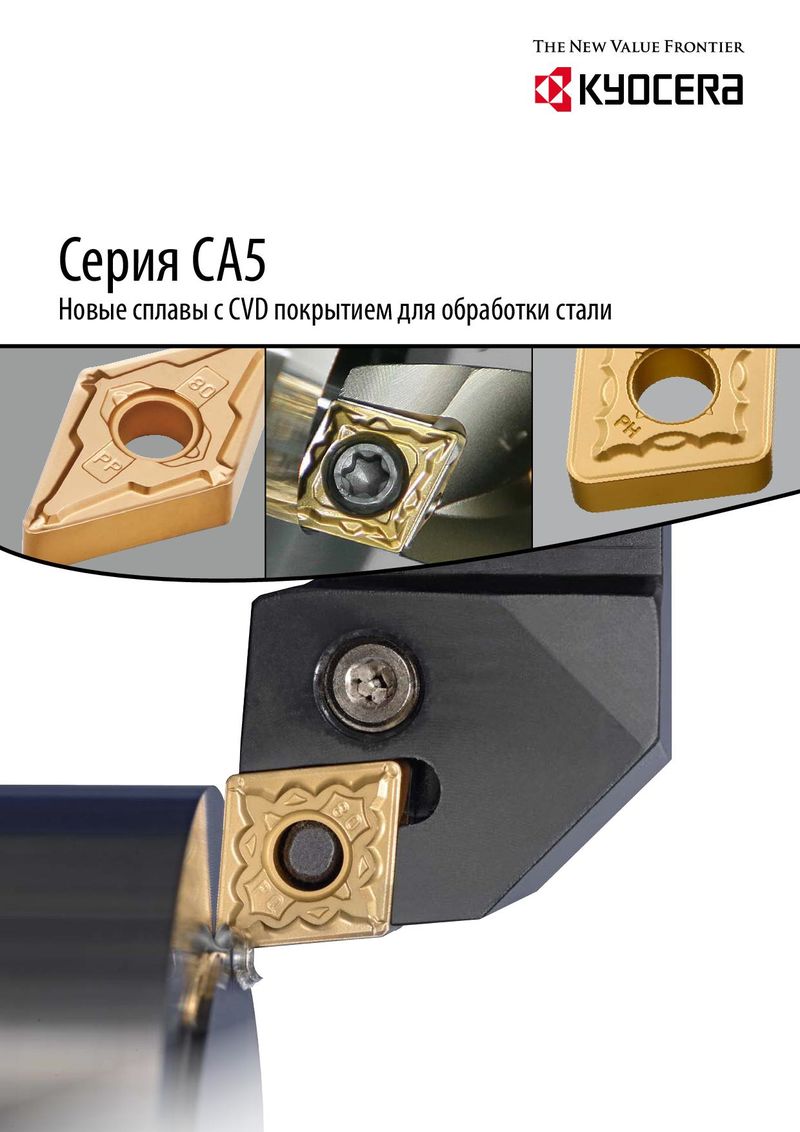 Каталог Kyocera пластины с CVD покрытием для обработки стали
 - Cover
- Chapter Overview
- Contents
- Introduction
- Introduction
- Negative-Chipbreaker
- Positive-Chipbreaker
- Page Guide
- Cermet / coated carbide / carbide lineup
- Negative inserts 80° Rhombic
- 55° Rhombic
- 55° Parallelogramm
- Round
- 90° Square
- 90° Square
- 60° Triangle
- 35° Rhombic
- 80° Trigon
- Small double sided tools
- 80° Rhombic
- 55° Rhombic
- 55° Rhombic
- 70° Rhombic
- Round
- 90° Square
- 90° Square
- 60° Triangle
- 60° Triangle
- 35° Rhombic
- 35° Rhombic
- 80° Trigon
- Bearing machining Round / Square-Type
- Inserts for back turning TKFB
- ABS / ABW
- Ceramic lineup
- Negative inserts 80° Rhombic
- 55° Rhombic
- 75° Rhombic
- Round
- 90° Square
- 60° Triangle
- 35° Rhombic
- Positive inserts Round
- Square
- Triangle
- Inserts for high hardened roll
- Grooving inserts
- CBN Lineup
- Introduction
- Solid bar EZB-NB
- GMN
- GDGS
- Grooving inserts GBA
- 80° Trigon
- 35° Rhombic
- 60° Triangle
- 55° Rhombic
- Positive inserts 80° Rhombic
- 60° Triangle / Solid
- 90° Square / Solid
- Round / Solid
- 80° Rhombic / Solid
- 80° Trigon
- 35° Rhombic
- 60° Triangle
- 90° Square
- 55° Rhombic
- Negative inserts 80° Rhombic
- PCD Lineup
- Introduction
- Milling inserts Available inserts
- VNBR-NB
- VNGR-NB
- Solid bar EZB-NB
- TKF
- GMGW
- GMN
- GDGS
- GV/GVF
- Grooving inserts GBA/TGF
- 80° Trigon
- 35° Rhombic
- 60° Triangle
- 90° Square
- 55° Rhombic
- Positive inserts 80° Rhombic
- 80° Trigon
- 35° Rhombic
- 60° Triangle
- 55° Rhombic
- Negative inserts 80° Rhombic
- Introduction
- Toolholders for general purpose
- CN insert DCLN/DCLN-JCT/PCLN
- DN insert DDJN/DDJN-JCT/DDHN
- PDJN/PDHN
- SN insert DSBN/PSBN/PSKN
- PSSN/PSDN
- TN insert DTGN/PTGN/PTFN
- WTJN/WTKN/WTEN
- VN insert DVLN/DVPN/DVVN
- MVLN/MVVN
- PVLN/PVPN/PVVN
- RC insert PRGC/PRXC
- RN insert PRGN
- WN Insert DWLN/DWLN-JCT/PWLN/WWLN
- Toolholders for ceramic inserts
- Selection guide for ceramic inserts
- RN insert CRSN/CRDN
- SN insert CSRN/CS-N/CSKN/CSYN/CSSN/CSDN
- EN insert CELN
- DN insert CDJN
- CN insert CCLN
- TN insert CTJN/CTUN
- Toolholders for CBN inserts
- CNMN insert CCRN-A/CCLN-A
- RNMN insert CRSN-A/CRDN-A
- SNMN insert CSRN-A/CSKN-A/CSSN-A/CSDN-A
- TNMN insert CTJN-A/CTUN-A
- Toolholders for bearing machining
- RCMT insert PRGC-BE
- SNMF insert CBSN
- Recommended cutting conditions
- Introduction
- Toolholders for back turning
- TKFB insert TKFB
- KTKF / KTKF Goose-neck holder
- ABS15 insert AABS-40F/SABS-40F
- ABW15 insert AABW-40F/SABW-40F
- ABW23 insert AABW-50F/SABW-50F
- Goose-neck toolholders
- DC insert SDJC
- VP insert SVLP
- External toolholders
- CC insert ACLC-FF
- SCLC
- SCLC-FF/SCLC-FFJCT
- DC insert ADJC-FF
- SDJC-FF
- SDJC-FFJCT
- SDJC
- SDLC-FF
- SDXC
- SDNC-F
- SDNC
- DP insert SDLP-FF
- TC/TP insert STGC
- STGP
- VB/VC insert AVJB-FF/SVJB-FF/SVJB-FFJCT/SVJB/SVPB/SVVB
- SVJC-FF/SVLC-FF
- SVPC-FF/SVVC
- VP insert SVJP-FF/SVJP-FFJCT/SVLP-FF/SVPP-FF
- External sleeve holders
- CC insert S...SCLC
- DC insert S...SDUC/S...SDLC
- VB/VC insert S...SVUB/S...SVUC
- Toolholders for small double sided tooling
- CN insert SCLN-FF (without offset)
- DN insert SDLN-FF (without offset)
- TN insert STLN-FF (without offset)
- Toolholders for double sided tooling for automatic lathes
- CN insert PCLN-FF (without offset)
- TN insert PTLN-FF (without offset)
- Recommended cutting conditions
- Introduction
- Solid tip bars for micro boring
- System Tip-Bars VNB type
- VNBX-S
- TWB
- STW/S-STW
- TWBT
- Dynamic-Bars
- CC insert A/S-SCLC-AE
- CP insert A-SCLP-AE
- DC insert A-SDUC-AE
- JC insert C-SJLC
- TC insert A-STLC-AE
- TB/TP insert S-STLB-AE
- VB/VC/VP insert A-SVJP-AE/A-SVJC-AE/A-SVJB-AE
- WB/WP insert S-SWUB-AE/A-SWUP-AE
- Borings bars (screw clamp / top clamp)
- SP insert S-SSKP/S-CSKP
- TP insert S-CTUP
- Bearing machining
- RPMT insert SRCP-B
- SNMF insert CBSN-B
- AD Bars
- CN insert HA-PCLN
- DN insert HA-PDUN
- TN insert HA-PTFN
- CC insert HA-SCLC
- DC insert HA-SDUC
- Boring adapter for AD Bars AD type with dampener system
- Boring bars for negative type inserts
- CN insert A-DCLN
- DN insert S-PDUN/A-PDUN (11)
- SN insert A-DSKN
- TN insert A-DTFN
- WN insert S-PWLN/A-PWLN
- Boring bars for ceramic inserts
- Boring bars for CBN inserts
- Technical information
- Applicable sleeves
- Introduction
- External grooving
- GBA type GBA
- KGB/KGBS
- GBF-KGBF-JCT
- TGF type TGF
- S-KGBF
- KTGF-F/KTGF/S-KTGF
- KGD
- KGD-JCT (Integral type)
- KGD (Integral type for automatic lathes)
- KGD (Integral type)
- KGDF S separate type
- GMGW type GMGW
- GH/GHU/GA type GH/GHU/GA
- GM/GMN/GMM/GMG/GMGA/FGG type GM/GMN/GMM/GMG/GMGA/FGG
- Internal grooving
- KGIA
- GIA type GIA
- GMM/GMG/GMGA type GMM/GMG/GMGA
- GH/GHU type GH/GHU
- GBA type KIGBA
- GDM type GDM
- GV type GV
- SIGE-WH-90 carbide shank bar (for automatic lathe; with coolant hole)
- SIGE-WH carbide shank bar (with coolant hole)
- SIGE-EH Excellent Bar (with coolant hole)
- GE/GER type GE/GER
- GC type GC
- VNG type VNG
- GMM
- Face grooving
- KGDF-Z (Integral type)
- GDFM/GDFMS type GDFM/GDMFS
- TWFG/TWFGT small diameter face grooving (Twin-Bars) TWFG
- VNFG type VNFG
- KGDF 0° separate type
- KGDF 90 separate type
- FTK type FTK
- GMM/GMG/GMGA type GMM/GMG/GMGA
- FMM/FMN type FMM/FMN
- GIFV (A/B/C)
- GFV\AA
- GVF type GVF
- Grooving
- Introduction
- Small diameter cut-off
- TKF type TKF
- KTKF
- KTKF-JCT
- KTKFS
- TKFS type TKFS
- KTKF-S
- KGD type
- GDM/GDMS/GDG type GDM/GDMS/GDG
- KGD (Integral type for automatic lathe)
- KGDS (for sub spindle tooling)
- KGD-JCT (Integral type)
- KGD (Integral type)
- KGD-JCT (Integral type for automatic lathe)
- KGD-JCT
- KGDS separate type
- KGM type
- GMM/GMN/GMR/GML type GMM/GMN/GMR/GMLw
- KGM/KGM-T/KGMM/KGMS
- 1-edge cut-off inserts
- TKN/TK type TKN/TK
- KTKB-SS/KTKB-S
- Toolblocks
- KTKH-S (Integral type)
- Introduction
- Threading inserts
- Metric External threading / 60° full profile
- Internal threading / 60° full profile
- Unified External threading / 60° full profile
- Internal threading / 60° full profile
- Parallel pipe, Whitworth External threading
- Internal threading
- Tapered pipe External threading / 55° full profile
- Internal threading / 55° full profile
- American national tapered pipe External threading
- Internal threading
- 60° type (Partial profile/M, UN) External threading
- Internal threading
- 55° type (Partial profile/G, R, Rc, W) External threading
- Internal threading
- 30° type (Trapezoidal) External threading
- Internal threading
- Threading toolholders
- External toolholders KTN/KTNS/KTN-JCT
- S-KTN
- Internal toolholders SIN/CIN
- Multipurpose threading tools
- TKFT for small parts machining TKFT
- KTKF
- TTX for small parts machining TTX
- KTTX/S-KTTX
- TT for external and internal threading TT
- KTT (external)
- KITG (internal)
- System Bar for micro internal threading VNT
- TPGB for internal threading TPGB
- S-STWP/S-STWP-E
- Recommended cutting conditions
- Depth of cut and number of passes
- Applicable toolholders and inserts
- Threading methods
- Threading methods and basic profiles
- Thread types
- Introduction
- MagicDrill DRA
- SF-DRA 12 DC
- SF-DRA 8 DC
- SF-DRA 5 DC
- SF-DRA 3 DC
- Flanged shank SF SF-DRA 1.5 DC
- Chamfering attachment for SS-DRA CH\-DRA
- SS-DRA 8 DC
- SS-DRA 5 DC
- SS-DRA 3 DC
- Straight shank SS SS-DRA 1.5 DC
- Recommended cutting conditions
- MagicDrill DRC
- Straight shank SS SS-DRC 3 DC
- SS-DRC 5 DC
- SS-DRC 8 DC
- Chamfering attachment for SS-DRC CH\-DRC
- Flanged shank SF SF-DRC 3 DC
- SF-DRC 5 DC
- SF-DRC 8 DC
- Recommended cutting conditions
- MagicDrill DRV
- Chamfering attachment for DRV CH\-DRV
- DRV 6 DC
- DRV 5 DC
- DRV 4 DC
- DRV 3 DC
- Toolholder DRV DRV 2 DC
- Recommended cutting conditions
- Adjustable sleeve (DRV/DRZ/DRX)
- MagicDrill DRZ
- Toolholder DRZ DRZ 2 DC
- DRZ 3 DC
- DRZ-CR
- Recommended cutting conditions
- MagicDrill DRS
- MagicDrill DRX
- Trouble shooting (DRV / DRX / DRZ / DRX)
- Lathe installation DRX/DRZ
- MagicDrill DRW
- Introduction
- Introduction
- ISO identification
- MFPN Series MFPN66
- MFK / MFK-SF
- MOF45 OFMT
- Lead angle 15°
- MSRS15 SPMT
- Lead angle 0°/ 2°
- MEW LOMU/LOGT
- MEC/MECX BDGT/BDMT
- MEWH LOMU/LOGT
- MEV TOMT
- MECH/MECHT BDMT
- MECH/MECHT MECHT
- MFWN WNEU/WNMU/WNGT
- MFSN88 SNMU
- MFLN90 LOGU
- MSRS90 SPMT
- MSR / MSR-BT50 APMT
- DMC/DMC-SX/DMC-H NDCT/NDCW/NDMM
- MFAH ENET
- MEAS KCGT
- High feed cutter
- MFH Series SOMT/LOGU/LPGT
- MFH Series MFH Mini
- MFH Series MFH Micro
- Multi-Function end mill
- Applicable inserts GOMT/JOMT
- Slott mill
- Ball-nose / radius type cutters
- MRF/MRFW RDFG
- MRW ROMU
- MRX RDMT/RDGT/RPMT/RPGT
- Other applications
- MCSE (chamfering end mill)
- Square-type inserts MEF (bolt countersink end mill)
- S type inserts METS (T-Slot mill)
- MVG (ring grooving end milll for M/C)
- GVR/GVFR
- MGI (grooving end mill for M/C)
- Grooving GVR/GVFR
- Other inserts
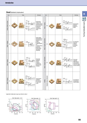
Finishing - Medium / up facingMedium - RoughingMedium - RoughingMedium - Roughingap (mm) ap (mm) Medium - RoughingMedium - Roughing / High Feed RateMedium - Roughing / High Feed RateRoughingap (mm) Standard (without indication) Turning indexable inserts Introduction Steel (Molded chipbreaker) B Name Design Advantages Name Design Advantages 0.1 0.2 • Improved chip 15° 7° curling at small 5° CJ 0.2 20° machining and highfeed rate machining• Improved chip HSevacuation at15°copying and up • General purposechipbreaker• Applicable to0.215°copying5° facing • Stable machining with good balance of 0.28 edge sharpness and PG strength0.08• Prevent chip5°15°clogging at high feedrate PT• Good chip control atlow feed rate 21° • Low cutting forceat high feed0.36machining• Land support13°structure • Stable machining with wide chip control range 0.12 0.1 GS • Strong edge27°8°chipbreaker• Stable for0.12continuous GTmachining andlight interrupted27°8°machining 12° 20° • Strong edge5°chipbreaker• Wide land design0.1and smooth chip12°20°control even at highfeed rate machining5° 0.25 15° 5° • General purpose 0.25 chipbreaker • Low cutting force PS • More stable due 5° 14° and applicable to 0.25 to large contact large ap roughing 15° surface 5° Applicable chipbreaker range (ap indicates radius) (Steel / Edge Length = 12, 16)5 (Steel / Edge Length = 12)5 (Steel / Edge Length = 16)10 Standard 4 GP 4 PG GT 8 PS (HS) 3 PQ CQ PS3(HS) 6 2 PP CJ 2 4 Standard 1 1 GS PT 2 CQ HQ 0.1 0.2 0.3 0.4 0.5 0.1 0.2 0.3 0.4 0.5 0.2 0.4 0.6 0.8 1.0 f (mm/rev) f (mm/rev) f (mm/rev) B5