Каталог Sumitomo специальные торцевые фрезы - страница 7
Навигация
 Техническая информация Sumitomo
 Каталог Sumitomo резьбонарезной инструмент
 Каталог Sumitomo микроинструмент
 Каталог Sumitomo твердосплавные заготовки
 Каталог Sumitomo инструмент для отрезки
 Каталог Sumitomo запасные части
- H001
- H002
- H003
- H004
- H005
- H006
- H007
- H008
- H009
- H010
- H011
- H012
- H013
- H014
- H015
- H016
- H017
- H018
- H019
- H020
- H021
- H022
- H023
- H024
- H025
- H026
- H027
- H028
- H029
- H030
- H031
- H032
- H033
- H034
- H035
- H036
- H037
- H038
- H039
- H040
- H041
- H042
- H043
- H044
- H045
- H046
- H047
- H048
- H049
- H050
- H051
- H052
- H053
- H054
- H055
- H056
- H057
- H058
- H059
- H060
- H061
- H062
- H063
- H064
- H065
- H066
- H067
- H068
- H069
- H070
- H071
- H072
- H073
- H074
- H075
- H076
- H077
- H078
- H079
- H080
- H081
- H082
- H083
- H084
- H085
- H086
- H087
- H088
- H089
- H090
- H091
- H092
- H093
- H094
- H095
- H096
- H097
- H098
- H099
- H100
- H101
- H102
- H103
- H104
- H105
- H106
- H107
- H108
- H109
- H110
- H111
- H112
- H113
- H114
- H115
- H116
- H117
- H118
- H119
- H120
- H121
- H122
- H123
- H124
- H125
- H126
- H127
- H128
- H129
- H130
- H131
- H132
- H133
- H134
- H135
- H136
- H137
- H138
- H139
- H140
- H141
- H142
- H143
- H144
- H145
- H146
- H147
- H148
- H149
- H150
- H151
- H152
- H153
- H154
- H155
- H156
- H157
- H158
- H159
- H160
- H161
- H162
- H163
- H164
- H165
- H166
- H167
- H168
- H169
- H170
- H171
- H172
- H173
- H174
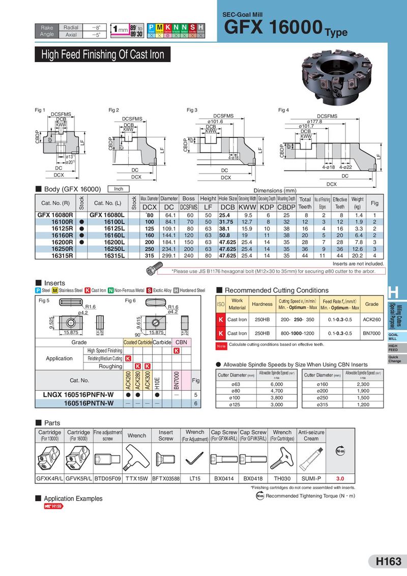
SEC-Goal Mill Rake Radial −8° 1mm 89°to P MK N N SH GFX 16000 Type Angle Axial 89°30′ Steel Stainless Steel Cast Iron Non-Ferrous Metal Aluminum Exotic Alloy Hardened Steel −5° H H G H H H H High Feed Finishing Of Cast Iron Fig 1 DCSFMS Fig 2 Fig 3 Fig 4 DCB DCSFMS DCSFMS DCSFMS KWW DCB ø101.6 ø177.8 KWW DCB ø101.7 CBDP KWW DCB KDP CBDP CBDP KDP KWW LF KDP CBDP KDP LF LF ø13*1 4-ø18 LF ø20*2 DC DC DC 4-ø18 4-ø22 DCX DCX DCX DC ■ Body (GFX 16000) DCX Inch Dimensions (mm) Cat. No. (R) Stock Cat. No. (L) Stock Max. Diameter Diameter Boss Height Hole Size Grooving Width Grooving Depth Mounting Depth Total No. of Finishing Effective Weight Fig DCX DC DCSFMS LF DCB KWW KDP CBDP Teeth Edges Teeth (kg) GFX 16080R GFX 16080L *80 64.1 60 50 25.4 9.5 6 25 8 2 8 1.4 1 16100R D 16100L 100 84.1 70 50 31.75 12.7 8 32 12 3 12 1.9 2 16125R D 16125L 125 109.1 80 63 38.1 15.9 10 38 16 4 16 3.3 2 16160R D 16160L 160 144.1 120 63 50.8 19 11 38 20 5 20 6.4 2 16200R D 16200L 200 184.1 150 63 47.625 25.4 14 35 28 7 28 7.8 3 16250R 16250L 250 234.1 200 63 47.625 25.4 14 35 36 9 36 12.6 3 16315R 16315L 315 299.1 240 80 47.625 25.4 14 35 44 11 44 20.2 4 Inserts are not included. *Please use JIS B1176 hexagonal bolt (M12×30 to 35mm) for securing ø80 cutter to the arbor. ■ Inserts H P Steel M Stainless Steel K Cast Iron N Non-Ferrous Metal S Exotic Alloy H Hardened Steel ■ Recommended Cutting Conditions Fig 5 Fig 6 ISO Work Hardness Cutting Speed (c m/min) Feed Rate (z mm/t) Grade (Special Purpose) R1.6 R1.6 Material Min. - Optimum - Max Min. - Optimum - Max Milling Cutters ø4.2 ø4.2 9.525 9.615 K Cast Iron 250HB 200- 250- 350 0.1- 0.3 -0.5 ACK260 15.875 4.76 90˚ 15.875 4.76 K Cast Iron 250HB 800- 1000 -1200 0.1- 0.3 -0.5 BN7000 GOAL Grade Coated Carbide Carbide CBN MILL Note Calculate cutting conditions based on effective teeth. HIGH High Speed Finishing K FEED Application Finishing/Medium Cutting K Quick ● Allowable Spindle Speeds by Size When Using CBN Inserts Change Roughing K K ACK260 ACK280 ACK300 BN7000 Cutter Diameter (mm) Allowable Spindle Speed (min-1) Cutter Diameter (mm) Allowable Spindle Speed (min-1) Cat. No. H10E Fig n max. n max. ø63 6,000 ø160 2,300 LNGX 160516PNFN-W D D D Q 5 ø80 4,700 ø200 1,900 ø100 3,800 ø250 1,500 160516PNTN-W Q Q Q Q 6 ø125 3,000 ø315 1,200 ■ Parts Cartridge Cartridge Fine adjustment Wrench Insert Wrench Cap Screw Cap Screw Wrench Anti-seizure (For 13000) (For 16000) screw Screw (For Adjustment) (For GFXK4R/L) (For GFVK5R/L) (For Cartridges) Cream Nm GFXK4R/L GFVK5R/L BTD05F09 T T X15W BF TX03588 LT15 BX0414 BX0418 TH030 SUMI-P 3.0 *Finishing cartridges do not come assembled with inserts. ■ Application Examples N m Recommended Tightening Torque (N・m) H159 H163