Каталог Sumitomo специальные торцевые фрезы - страница 13
Навигация
 Техническая информация Sumitomo
 Каталог Sumitomo резьбонарезной инструмент
 Каталог Sumitomo микроинструмент
 Каталог Sumitomo твердосплавные заготовки
 Каталог Sumitomo инструмент для отрезки
 Каталог Sumitomo запасные части
- H001
- H002
- H003
- H004
- H005
- H006
- H007
- H008
- H009
- H010
- H011
- H012
- H013
- H014
- H015
- H016
- H017
- H018
- H019
- H020
- H021
- H022
- H023
- H024
- H025
- H026
- H027
- H028
- H029
- H030
- H031
- H032
- H033
- H034
- H035
- H036
- H037
- H038
- H039
- H040
- H041
- H042
- H043
- H044
- H045
- H046
- H047
- H048
- H049
- H050
- H051
- H052
- H053
- H054
- H055
- H056
- H057
- H058
- H059
- H060
- H061
- H062
- H063
- H064
- H065
- H066
- H067
- H068
- H069
- H070
- H071
- H072
- H073
- H074
- H075
- H076
- H077
- H078
- H079
- H080
- H081
- H082
- H083
- H084
- H085
- H086
- H087
- H088
- H089
- H090
- H091
- H092
- H093
- H094
- H095
- H096
- H097
- H098
- H099
- H100
- H101
- H102
- H103
- H104
- H105
- H106
- H107
- H108
- H109
- H110
- H111
- H112
- H113
- H114
- H115
- H116
- H117
- H118
- H119
- H120
- H121
- H122
- H123
- H124
- H125
- H126
- H127
- H128
- H129
- H130
- H131
- H132
- H133
- H134
- H135
- H136
- H137
- H138
- H139
- H140
- H141
- H142
- H143
- H144
- H145
- H146
- H147
- H148
- H149
- H150
- H151
- H152
- H153
- H154
- H155
- H156
- H157
- H158
- H159
- H160
- H161
- H162
- H163
- H164
- H165
- H166
- H167
- H168
- H169
- H170
- H171
- H172
- H173
- H174
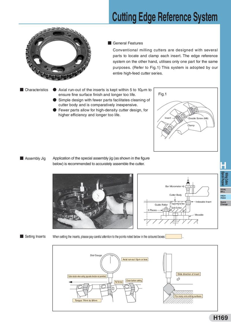
Cutting Edge Reference System ■ General Features Conventional milling cutters are designed with several parts to locate and clamp each insert. The edge reference system on the other hand, utilises only one part for the same purposes. (Refer to Fig.1) This system is adopted by our entire high-feed cutter series. ■ Characteristics ● Axial run-out of the inserts is kept within 5 to 10μm to ensure fine surface finish and longer too life. Fig.1 ● Simple design with fewer parts facilitates cleaning of cutter body and is comparatively inexpensive. ● Fewer parts allow for high-density cutter design, for higher efficiency and longer too life. Insert Double Screw (M8) Clamp ■ Assembly Jig Application of the special assembly jig (as shown in the figure below) is recommended to accurately assemble the cutter. H (Special Purpose) Milling Cutters Bar Micrometer GOAL MILL Cutter Body HIGH FEED Supporting Surface Indexable Insert Quick Guide Roller Change Guide Surface 3 Places Movable ■ Setting Inserts When setting the inserts, please pay careful attention to the points noted below in the coloured boxes . Dial Gauge Axial run-out 10μm or less Slide direction of insert Cutter rotation when setting (opposite direction not permitted) Flat Terminal Clean before setting Fits nicely onto sliding surfaces Torque 7N m to 8N m H169