Каталог Sumitomo специальные торцевые фрезы - страница 6
Навигация
 Техническая информация Sumitomo
 Каталог Sumitomo резьбонарезной инструмент
 Каталог Sumitomo микроинструмент
 Каталог Sumitomo твердосплавные заготовки
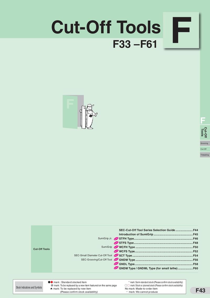 Каталог Sumitomo инструмент для отрезки
 Каталог Sumitomo запасные части
- H001
- H002
- H003
- H004
- H005
- H006
- H007
- H008
- H009
- H010
- H011
- H012
- H013
- H014
- H015
- H016
- H017
- H018
- H019
- H020
- H021
- H022
- H023
- H024
- H025
- H026
- H027
- H028
- H029
- H030
- H031
- H032
- H033
- H034
- H035
- H036
- H037
- H038
- H039
- H040
- H041
- H042
- H043
- H044
- H045
- H046
- H047
- H048
- H049
- H050
- H051
- H052
- H053
- H054
- H055
- H056
- H057
- H058
- H059
- H060
- H061
- H062
- H063
- H064
- H065
- H066
- H067
- H068
- H069
- H070
- H071
- H072
- H073
- H074
- H075
- H076
- H077
- H078
- H079
- H080
- H081
- H082
- H083
- H084
- H085
- H086
- H087
- H088
- H089
- H090
- H091
- H092
- H093
- H094
- H095
- H096
- H097
- H098
- H099
- H100
- H101
- H102
- H103
- H104
- H105
- H106
- H107
- H108
- H109
- H110
- H111
- H112
- H113
- H114
- H115
- H116
- H117
- H118
- H119
- H120
- H121
- H122
- H123
- H124
- H125
- H126
- H127
- H128
- H129
- H130
- H131
- H132
- H133
- H134
- H135
- H136
- H137
- H138
- H139
- H140
- H141
- H142
- H143
- H144
- H145
- H146
- H147
- H148
- H149
- H150
- H151
- H152
- H153
- H154
- H155
- H156
- H157
- H158
- H159
- H160
- H161
- H162
- H163
- H164
- H165
- H166
- H167
- H168
- H169
- H170
- H171
- H172
- H173
- H174
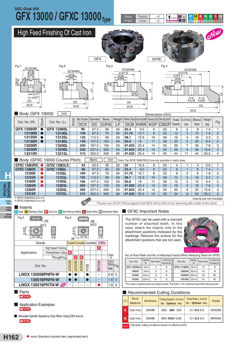
SEC-Goal Mill GFX 13000 / GFXC 13000Type Rake Radial −8° 1mm 89°to P M K N N SH Angle Axial 89°30′ Steel Stainless Steel Cast Iron Non-Ferrous Metal Aluminum Exotic Alloy Hardened Steel −5° H H G H H H H High Feed Finishing Of Cast Iron GFX GFXC Fig 1 DCSFMS Fig 2 Fig 3 Fig 4 DCB DCSFMS DCSFMS DCSFMS KWW DCB ø101.6 ø177.8 KWW DCB ø101.7 CBDP KWW DCB KDP CBDP CBDP KDP KWW LF KDP CBDP KDP LF LF ø13*1 4-ø18 LF ø20*2 DC DC DC 4-ø18 4-ø22 DCX DCX DCX DC ■ Body (GFX 13000) DCX Inch Dimensions (mm) Cat. No. (R) Stock Cat. No. (L) Stock Max. Diameter Diameter Boss Height Hole Size Grooving Width Grooving Depth Mounting Depth Total No. of Finishing Effective Weight Fig DCX DC DCSFMS LF DCB KWW KDP CBDP Teeth Edges Teeth (kg) GFX 13080R D GFX 13080L *80 67.3 60 50 25.4 9.5 6 25 8 2 8 1.4 1 13100R D 13100L 100 87.3 70 50 31.75 12.7 8 32 12 3 12 1.9 2 13125R D 13125L 125 112.3 80 63 38.1 15.9 10 38 16 4 16 3.3 2 13160R D 13160L 160 147.3 120 63 50.8 19 11 38 20 5 20 6.4 2 13200R 13200L 200 187.3 150 63 47.625 25.4 14 35 28 7 28 7.8 3 13250R 13250L 250 237.3 200 63 47.625 25.4 14 35 36 9 36 12.6 3 13315R 13315L 315 302.3 240 80 47.625 25.4 14 35 44 11 44 20.2 4 ■ Body (GFXC 13000 Course Pitch) Metric Inch Note: The GFXC13063 RS/LS are only available in metric sizes. GFXC 13063RS D GFXC 13063LS 63 50.3 50 50 22 10.4 6 20 4 1 4 0.9 1 GFXC 13080R D GFXC 13080L *80 67.3 60 50 25.4 9.5 6 25 6 1 6 1.4 1 H 13100R D 13100L 100 87.3 70 50 31.75 12.7 8 32 8 2 8 1.9 2 13125R D 13125L 125 112.3 80 63 38.1 15.9 10 38 10 2 10 3.3 2 (Special Purpose) 13160R D 13160L 160 147.3 120 63 50.8 19 11 38 12 3 12 6.4 2 Milling Cutters 13200R D 13200L 200 187.3 150 63 47.625 25.4 14 35 16 4 16 7.8 3 13250R 13250L 250 237.3 200 63 47.625 25.4 14 35 20 5 20 12.6 3 13315R 13315L 315 302.3 240 80 47.625 25.4 14 35 24 6 24 20.2 4 *1 GFXC13063RS/LS is ø11. Inserts are not included. GOAL *2 GFXC13063RS/LS is ø18. MILL *Please use JIS B1176 hexagonal bolt (M12×30 to 35mm) for securing ø80 cutter to the arbor. HIGH ■ Inserts FEED P Steel M Stainless Steel K Cast Iron N Non-Ferrous Metal S Exotic Alloy H Hardened Steel ■ GFXC Important Notes Quick Change Fig 5 Fig 6 RE RE The GFXC can be used with a reduced ø4.2 ø4.2 number of attached teeth. In this 9.525 9.615 case, attach the inserts only to the attachment positions indicated by the Markings 12.700 4.76 90˚ 12.70 4.76 markings. Remove the screws for the attachment positions that are not used. Grade Coated Carbide Carbide CBN High Speed Finishing K Attach the inserts only to the attachment Application Finishing/Medium Cutting K positions indicated by the markings. Roughing K K Dimensions No. of Total Teeth and No. of Attached Inserts When Reducing Teeth for GFXC (mm) Diameter No.ofAtached Inserts Diameter No.ofAtached Inserts ACK260 ACK280 ACK300 BN7000 Corner Cat. No. Total Teeth Cat. No. Total Teeth Radius Fig DC When Reducing Teeth DC When Reducing Teeth H10E Cat. No. GFXC 13063RS/LS 63mm 4 2 GFXC 13160R/L 160mm 12 6 RE 13080R/L 80mm 6 2 13200R/L 200mm 16 8 LNGX 130508PNFN-W D D D Q 0.8 5 13100R/L 100mm 8 4 13250R/L 250mm 20 10 130516PNFN-W D D D Q 1.6 5 13125R/L 125mm 10 4 13315R/L 315mm 24 12 LNGX 130516PNTN-W Q Q Q Q D 1.6 6 * The number of attached inserts must always be either "Total Teeth" or "No. of Attached Inserts When Reducing Teeth". ■ Parts ■ Recommended Cutting Conditions H163 Work Cutting Speed vc (m/min) Feed Rate fz (mm/t) ISO Material Hardness Min. - Optimum - Max. Min. - Optimum - Max. Grade ■ Application Examples H159 K Cast Iron 250HB 200- 250- 350 0.1- 0.3 -0.5 ACK260 ● Allowable Spindle Speeds by Size When Using CBN Inserts K Cast Iron 250HB 800- 1000 -1200 0.1- 0.3 -0.5 BN7000 H163 Note Calculate cutting conditions based on effective teeth. H162 D mark: Standard stocked item (expanded item)