Каталог Sumitomo резьбонарезной инструмент - страница 14
Навигация
 Каталог Sumitomo фрезы со сменными пластинами
 Каталог Sumitomo пластины с кубическим нитридом бора Sumiboron
 Каталог Sumitomo инструмент для обработки канавок
 Общий каталог Sumitomo 2018 - 2019
 Каталог Sumitomo твердосплавные заготовки
 Каталог Sumitomo модульные системы для револьверных головок токарных станков
 - F001
- F002
- F003
- F004
- F005
- F006
- F007
- F008
- F009
- F010
- F011
- F012
- F013
- F014
- F015
- F016
- F017
- F018
- F019
- F020
- F021
- F022
- F023
- F024
- F025
- F026
- F027
- F028
- F029
- F030
- F031
- F032
- F033
- F034
- F035
- F036
- F037
- F038
- F039
- F040
- F041
- F042
- F043
- F044
- F045
- F046
- F047
- F048
- F049
- F050
- F051
- F052
- F053
- F054
- F055
- F056
- F057
- F058
- F059
- F060
- F061
- F062
- F063
- F064
- F065
- F066
- F067
- F068
- F069
- F070
- F071
- F072
- F073
- F074
- F075
- F076
- F077
- F078
- F079
- F080
- F081
- F082
- F083
- F084
- F085
- F086
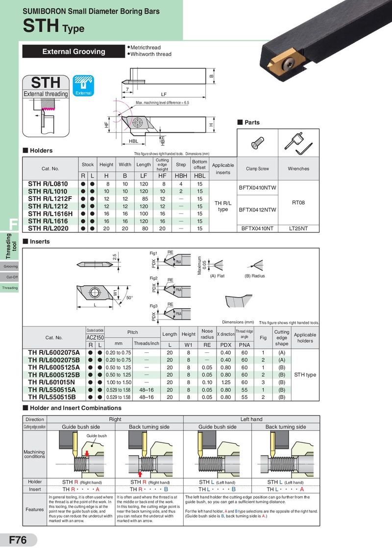
SUMIBORON Small Diameter Boring Bars STH Type External Grooving ● Metricthread ● Whitworth thread STH B External threading External 7 LF Max. machining level difference = 6.5 HF H ■ Parts HBL HBH ■ Holders This figure shows right handed tools. Dimensions (mm) Cutting Bottom Stock Height Width Length edge Step offset Applicable Cat. No. height inserts Clamp Screw Wrenches R L H B LF HF HBH HBL STH R/L0810 D D 8 10 120 8 4 15 BFTX0410NTW STH R/L1010 D D 10 10 120 10 2 15 STH R/L1212F D D 12 12 85 12 Q 15 TH R/L RT08 STH R/L1212 D D 12 12 120 12 Q 15 type BFTX0412NTW STH R/L1616H D D 16 16 100 16 Q 15 F STH R/L1616 D D 16 16 120 16 Q 15 STH R/L2020 D D 20 20 80 20 Q 15 BFTX0410NT LT25NT Threading tool ■ Inserts 2.5 Fig1 RE PDX PNA Maximum 0.05 Grooving Cut-Off Fig2 (A) Flat (B) Radius RE Threading W1 PDX PNA 50° L Fig3 RE PDX PNA Dimensions (mm) This figure shows right handed tools. Coated carbide Pitch Length Height Nose X direction Thread ridge Cutting Cat. No. ACZ150 radius angle Fig edge Applicable R L mm Threads/inch L W1 RE PDX PNA shape holders TH R/L6002075A D D 0.20 to 0.75 Q 20 8 Q 0.40 60 1 (A) TH R/L6002075B D D 0.20 to 0.75 Q 20 8 Q 0.40 60 2 (A) TH R/L6005125A D D 0.50 to 1.25 Q 20 8 0.05 0.80 60 1 (B) TH R/L6005125B D D 0.50 to 1.25 Q 20 8 0.05 0.80 60 2 (B) STH type TH R/L601015N D D 1.00 to 1.50 Q 20 8 0.10 1.25 60 3 (B) TH R/L550515A D D 0.529 to 1.58 48–16 20 8 0.05 0.80 55 1 (B) TH R/L550515B D D 0.529 to 1.58 48–16 20 8 0.05 0.80 55 2 (B) ■ Holder and Insert Combinations Direction Right Left hand Cutting edge position Guide bush side Back turning side Guide bush side Back turning side Guide bush Machining conditions Holder STH R (Right hand) STH R (Right hand) STH L (Left hand) STH L (Left hand) Insert TH R・・・・A TH R・・・・B TH L・・・・B TH L・・・・A In general tooling, it is often used where It is often used where the thread is at The left hand holder the cutting edge position can go further from the the thread is at the point of the work. In the middle or back end of the work. guide bush, so you can get a sufficient turning distance. Features this tooling, the cutting edge is at the In this tooling, the cutting edge point is point near the guide bush side, and near the back turning side, and thus For the left hand holder, A and B type selections are the opposite of the right hand. thus you can reduce the undercut width you can reduce the undercut width (Guide bush side is B, back turning side is A.) marked with an arrow. marked with an arrow. F76