Общий каталог Mitsubishi 2020 - 2021 - страница 1354
Навигация
 Каталог Mitsubishi Materials запасные части
 Каталог Mitsubishi Materials резьбонарезной инструмент
 Каталог Mitsubishi Materials СНП с CBN и PCD для токарной обработки
 Каталог Mitsubishi Materials сверлильные инструменты
 Каталог Mitsubishi Materials расточной инструмент
 Каталог Mitsubishi Materials пластины для точения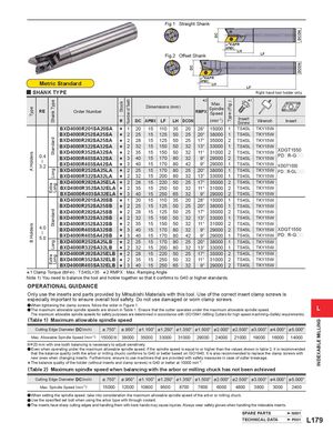
| Fi | g.1 S | traigh | t Shan | k | |||||||||||
| Met | ric Standard | Fi | g.2 f | DC Offset S | APMX K f hank | DC LH APR | APMX KA | LF LH PR | LF | DCON DCON | |||||
| y S | HAN | K TYPE | Right hand | tool holder only. | |||||||||||
| e | h | 2 | 1 | ||||||||||||
| p | k | e | M | .) | |||||||||||
| Type | RE | Order Number nk Ty | Stoc | ber of Te | Dime | nsions | (mm) | RMPX | ax. Spindle Speed | pe (Fig | |||||
| Sha | R | Num | DC | APMX | LF | LH | DCON | (min-1) | Ty | Insert Screw | Wrench | Insert | |||
| BXD4000R201SA20SA | s | 1 | 20 | 15 | 110 | 35 | 20 | 28° | 15000 | 1 | TS4SL | TKY15W | |||
| BXD4000R252SA25SA | s | 2 | 25 | 15 | 125 | 50 | 25 | 20° | 38000 | 1 | TS4SL | TKY15W | |||
| BXD4000R282SA25SA ard | s | 2 | 28 | 15 | 125 | 50 | 25 | 17° | 35000 | 2 | TS4SL | TKY15W | |||
| BXD4000R322SA32SA nd | s | 2 | 32 | 15 | 150 | 50 | 32 | 13° | 33000 | 1 | TS4SL | TKY15W | |||
| rs | BXD4000R352SA32SA Sta | s | 2 | 35 | 15 | 150 | 50 | 32 | 11° | 31000 | 2 | TS4SL | TKY15W | XDGT1550 | |
| lde | 0.4 | BXD4000R403SA32SA | s | 3 | 40 | 15 | 170 | 80 | 32 | 9° | 29000 | 2 | TS4SL | TKY15W | PDpR-Gpp |
| Ho | ─ 32 | BXD4000R403SA42SA | s | 3 | 40 | 15 | 170 | 80 | 42 | 9° | 29000 | 1 | TS4SL | TKY15W | XDGT1550 |
| A | . | BXD4000R252SA25LA ng | s | 2 | 25 | 15 | 170 | 80 | 25 | 20° | 38000 | 1 | TS4SL | TKY15W | PDpR-GLpp |
| BXD4000R322SA32LA Lo | s | 2 | 32 | 15 | 200 | 80 | 32 | 13° | 33000 | 1 | TS4SL | TKY15W | |||
| BXD4000R282SA25ELA a g | s | 2 | 28 | 15 | 220 | 50 | 25 | 17° | 35000 | 2 | TS4SL | TKY15W | |||
| BXD4000R352SA32ELA xtr on | s | 2 | 35 | 15 | 250 | 50 | 32 | 11° | 31000 | 2 | TS4SL | TKY15W | |||
| BXD4000R403SA32ELA E L | s | 3 | 40 | 15 | 250 | 65 | 32 | 9° | 29000 | 2 | TS4SL | TKY15W | |||
| BXD4000R201SA20SB | s | 1 | 20 | 15 | 110 | 35 | 20 | 28° | 15000 | 1 | TS4SL | TKY15W | |||
| BXD4000R252SA25SB | s | 2 | 25 | 15 | 125 | 50 | 25 | 20° | 38000 | 1 | TS4SL | TKY15W | |||
| BXD4000R282SA25SB ard | s | 2 | 28 | 15 | 125 | 50 | 25 | 17° | 35000 | 2 | TS4SL | TKY15W | |||
| BXD4000R322SA32SB nd | s | 2 | 32 | 15 | 150 | 50 | 32 | 13° | 33000 | 1 | TS4SL | TKY15W | |||
| s | BXD4000R352SA32SB Sta | s | 2 | 35 | 15 | 150 | 50 | 32 | 11° | 31000 | 2 | TS4SL | TKY15W | ||
| lder | 4.0 | BXD4000R403SA32SB | s | 3 | 40 | 15 | 170 | 80 | 32 | 9° | 29000 | 2 | TS4SL | TKY15W | XDGT1550 |
| Ho | ─ | BXD4000R403SA42SB | s | 3 | 40 | 15 | 170 | 80 | 42 | 9° | 29000 | 1 | TS4SL | TKY15W | PDpR-Gpp |
| B | 5.0 | BXD4000R252SA25LB ng | s | 2 | 25 | 15 | 170 | 80 | 25 | 20° | 38000 | 1 | TS4SL | TKY15W | |
| BXD4000R322SA32LB Lo | s | 2 | 32 | 15 | 200 | 80 | 32 | 13° | 33000 | 1 | TS4SL | TKY15W | |||
| BXD4000R282SA25ELB a g | s | 2 | 28 | 15 | 220 | 50 | 25 | 17° | 35000 | 2 | TS4SL | TKY15W | |||
| BXD4000R352SA32ELB xtr on | s | 2 | 35 | 15 | 250 | 50 | 32 | 11° | 31000 | 2 | TS4SL | TKY15W | |||
| BXD4000R403SA32ELB E L | s | 3 | 40 | 15 | 250 | 65 | 32 | 9° | 29000 | 2 | TS4SL | TKY15W |
*1 Clamp Torque (lbf-in) : TS4SL=35 *2 RMPX : Max. Ramping Angle
Note 1) You need to balance the tool and holder together so that it confirms to G40 or higher standards.
OPERATIONAL GUIDANCE
Only use the inserts and parts provided by Mitsubishi Materials with this tool. Use of the correct insert clamp screws is especially important to ensure overall tool safety. Do not use damaged or worn clamp screws. aWhen tightening the clamp screws, follow the order in Figure 1. L aThe maximum allowable spindle speeds are shown in Table 1. Ensure that the cutter operates under the maximum allowable spindle speed. The maximum allowable spindle speeds for safety purposes are determined in accordance with ISO15641 (Milling Cutters for high speed machining–Safety requirements). (Table 1) Maximum allowable spindle speed
| Cutting Edge Diameter DC(inch) | ø.750" | ø.950" | ø1.100" | ø1.250" | ø1.350" | ø1.500" | ø2.000" | ø2.500" | ø3.000" | ø4.000" | ø5.000" |
| Max. Allowable Spindle Speed (min-1) | 15000 | 38000 | 35000 | 33000 | 31000 | 29000 | 24000 | 21000 | 19000 | 16000 | 14000 |
ø20 mm with one tooth balancing is necessary to adjust sensitively. a Even when operating under the maximum allowable spindle speed, if the spindle speed is equal to or higher than the values shown in table 2, it is recommended that the balance quality (with the arbor or milling chuck) conforms to G40 or better based on ISO1940. It is also recommended to replace the clamp screws with * new ones when changing inserts. Furthermore, ensure to use machines that are provided with safety measures in case of cutter breakage. The balance quality of the holder (without inserts and clamp screws) is G40 or better at 10000 min -1. (Table 2) Maximum spindle speed when balancing with the arbor or milling chuck has not been achieved
| Cutting Edge Diameter DC(inch) | ø.750" | ø.950" | ø1.100" | ø1.250" | ø1.350" | ø1.500" | ø2.000" | ø2.500" | ø3.000" | ø4.000" | ø5.000" |
| Max. Spindle Speed (min-1) | 15000 | 12000 | 10800 | 9500 | 8700 | 7600 | 6000 | 4800 | 3800 | 3000 | 2400 |
aWhen setting the spindle speed, take into consideration the maximum allowable spindle speed of the arbor or milling chuck. aUse the specified set bolt when using the arbor type with through coolant. aThe inserts have sharp cutting edges and handling them with bare hands may cause injuries. Always wear safety gloves when handling the indexable inserts.