Общий каталог Mitsubishi 2020 - 2021 - страница 1294
Навигация
 Каталог Mitsubishi Materials запасные части
 Каталог Mitsubishi Materials резьбонарезной инструмент
 Каталог Mitsubishi Materials СНП с CBN и PCD для токарной обработки
 Каталог Mitsubishi Materials сверлильные инструменты
 Каталог Mitsubishi Materials расточной инструмент
 Каталог Mitsubishi Materials пластины для точения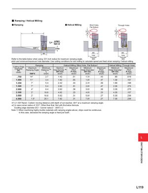
y Ramping / Helical Milling
a Ramping aa Helical Milling Blind Holes, Through Holes
Flat Bottom Pitch Pitch (P) (P)
APMX RMPX APMX
| DC | DC | DC | ||
| Hole | Hole | |||
| Diameter | Diameter | |||
| Refer to the table below when using .031 inch radius for maximum ramping angle, | (DH) | (DH) |
pitch and minimum/maximum hole diameter. Use cutting conditions for slot milling to calculate speed and feed when ramping / helical milling.
| Ram | ping | Helic | al Milling (Blin | d Hole,Flat Botto | m) | Helical Milling ( | Through Hole) | |
| Cutting Edge Diameter DC (inch) | Maximum Ramping Angle RMPX | Minimum Distance 1 L (inch) | Maximum Hole Diameter 2 DH max. (inch) | Maximum Pitch P max. (inch) | Minimum Hole Diameter DH min. (inch) | Maximum Pitch P max. (inch) | Minimum Hole Diameter DH min. (inch) | Maximum Pitch P max. (inch) |
| .750 | 14° | 2.7 | 1.42 | .51 | 1.31 | .43 | .80 | .019 |
| 1.000 | 11° | 3.4 | 1.92 | .55 | 1.81 | .47 | 1.30 | .157 |
| 1.250 | 7° | 5.4 | 2.42 | .43 | 2.31 | .39 | 1.80 | .196 |
| 1.500 | 7° | 5.4 | 2.92 | .51 | 2.81 | .47 | 2.30 | .275 |
| 2.000 | 4° | 9.4 | 3.92 | .39 | 3.81 | .39 | 3.30 | .275 |
| 2.500 | 2° | 18.8 | 4.92 | .23 | 4.81 | .23 | 4.30 | .157 |
| 3.000 | 2° | 18.8 | 5.92 | .31 | 5.81 | .27 | 5.30 | .236 |
| 4.000 | 1.5° | 25.1 | 7.92 | .31 | 7.81 | .27 | 7.30 | .236 |
*1 L(=.591"/tan%). Cutters' moving distance until depth of cut reaches .591" at a maximum ramping angle. *2 In case corner radius of .031". Other than that, find with the below formula. {(cutting edge diameter DC) - (corner radius) - .008"} x 2 Note 1) When machining highly ductile materials with ramping angles above, chips could be continuous. In this case, decrease the ramping angle or feed per tooth.