Общий каталог Mitsubishi 2020 - 2021 - страница 1737
Навигация
 Каталог Mitsubishi Materials запасные части
 Каталог Mitsubishi Materials резьбонарезной инструмент
 Каталог Mitsubishi Materials СНП с CBN и PCD для токарной обработки
 Каталог Mitsubishi Materials сверлильные инструменты
 Каталог Mitsubishi Materials расточной инструмент
 Каталог Mitsubishi Materials пластины для точения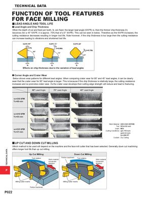
FOR FACE MILLING
LEAD ANGLE AND TOOL LIFEy
a Lead Angle and Chip Thickness
When the depth of cut and feed per tooth, fz, are fixed, the larger lead angle (KAPR) is, then the thinner chip thickness (h) becomes (for a 45° KAPR, it is approx. 75% that of a 0° KAPR). This can be seen in below. Therefore as the KAPR increases, the cutting resistance decreases resulting in longer tool life. Note however, if the chip thickness is too large then the cutting resistance can increase leading to vibrations and shortened tool life.
KAPR 90° KAPR 75° KAPR
90° 75° 45°
Effects on chip thickness due to the variation of lead angles
a Corner Angle and Crater Wear
Below shows wear patterns for different lead angles. When comparing crater wear for 90° and 45° lead angles, it can be clearly seen that the crater wear for 90° lead angle is larger. This is because if the chip thickness is relatively large, the cutting resistance increases and so promotes crater wear. As the crater wear develops then cutting edge strength will reduce and lead to fracturing.
90° Lead Angle 75° Lead Angle 45° Lead Angle
vc=330 SFM Tc=69 min
vc=410 SFM Tc=55 min
Work Material : AISI 4340 (287HB) Tool : DC=4.92 inch vc=525 SFM Insert : M20 Tc=31 min Cutting Conditions : ap=.118 inch ae=4.33 inch fz=.008 IPT Coolant : Dry Cutting
y UP CUT AND DOWN CUT MILLING
Which method to be used will depend on the machine and the face mill cutter that has been selected. Generally down cut machining offers longer tool life than up cut milling. Up Cut Milling Down Cut Milling
Tool rotation Portion machined Tool rotation
Work material Work material movement movement direction direction P
Milling cutter inserts Milling cutter inserts Portion machined