Общий каталог Mitsubishi 2020 - 2021 - страница 1370
Навигация
 Каталог Mitsubishi Materials запасные части
 Каталог Mitsubishi Materials резьбонарезной инструмент
 Каталог Mitsubishi Materials СНП с CBN и PCD для токарной обработки
 Каталог Mitsubishi Materials сверлильные инструменты
 Каталог Mitsubishi Materials расточной инструмент
 Каталог Mitsubishi Materials пластины для точения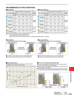
| y W | Slot Millin ork Material | g Sindle Seed Cuttin | g Cond | ition Vs.T | ool Diam | eter | Insert rd |
| p p Feed | &1" | &1.25" | &1.5" | &2" | gae | ||
| P | Mild Steel | min-1 | 2250 | 1800 | 1500 | 1100 | |
| ( | inch/min | 7─12 | 6─10 | 7─12 | 6─10 | ||
| Carbon Steel | min-1 | 2250 | 1800 | 1500 | 1100 | VP15TF | |
| (20HRC) | inch/min | 8─14 | 7─12 | 8─14 | 7─12 | F7030 | |
| Alloy Steel | min-1 | 1750 | 1800 | 1200 | 900 | ||
| (30HRC) | inch/min | 6─10 | 5─8 | 6─10 | 5─8 | ||
| M | Stainless Steel | min-1 | 1900 | 1500 | 1250 | 950 | VP15TF |
| (304) | inch/min | 3─5 | 2.5─4 | 3─5 | 2.5─4 | ||
| K | Gray Cast Iron | min-1 | 1800 | 1250 | 950 | 650 | UTi20T |
| ( | inch/min | 7─9 | 7─9 | 8─10 | 8─10 |
| y W | Shoulder ork Material | Milling Sindle Seed Cuttin | g Condi | tion Vs.T | ool Diam | eter | Insert rd |
| p p Feed | &1" | &1.25" | &1.5" | &2" | gae | ||
| P | Mild Steel | min-1 | 2250 | 1800 | 1500 | 1100 | |
| ( | inch/min | 11─18 | 9─15 | 11─18 | 9─15 | ||
| Carbon Steel | min-1 | 2250 | 1800 | 1500 | 1100 | VP15TF | |
| (20HRC) | inch/min | 12─21 | 11─18 | 12─21 | 11─18 | F7030 | |
| Alloy Steel | min-1 | 1750 | 1400 | 1200 | 900 | ||
| (30HRC) | inch/min | 9─15 | 8─12 | 9─15 | 8─12 | ||
| M | Stainless Steel | min-1 | 1900 | 1500 | 1250 | 950 | VP15TF |
| (304) | inch/min | 7─12 | 6─10 | 7─12 | 6─10 | ||
| K | Gray Cast Iron | min-1 | 1800 | 1250 | 950 | 650 | UTi20T |
| ( | inch/min | 8─10 | 8─10 | 9.5─11 | 9.5─11 |
Note 1) These feed rates are for ENA and ERA inserts. Reduce feed 25% for ENB and ERB inserts. ENB or ERB inserts not recommended in gummy materials like stainless steel or mild steel.
y Slot Milling y Shoulder Milling
Forced air is required at cutting edge Generally down (climb) cut is recommended
CONDITION I CONDITION II CONDITION I CONDITION II
(NOTE FEED RATE) (NOTE FEED RATE)
DC .25xDC .25xDC .5xDC
a Use higher recommended feed rate under CONDITION I. a Use higher recommended feed rate under CONDITION I. a Use lower recommended feed rate under CONDITION II. a Use lower recommended feed rate under CONDITION II.
y Net Cutting Power y For Use of Long Cutting Length Type
a Please use the chart below for reference, please select the Since the overhang from the milling chuck is long, a large width of a
| conditions that suits the machines power. | ÷ | cut will cause chattering and tool breakage. |
| aChip Discharge Q (inch3/min)=Table Feed×Depth of Cut×Cutting Width | 1000 | Keep the width of cut small and the depth of cut in axial direction large. |
a (See the following illustration.) aFor slot milling, keep the table feed at not more than half the value listed in L the above table. (Use the standard cutting length type as much as possible.)
(HP
(Steel 230HB
Not Good Good
| Metal Removal (Cubic inch) | Large Depth of Cut | Small Depth of Cut |
| (.5xDC .25xDC) | ( .25xDC) |