Общий каталог Mitsubishi 2020 - 2021 - страница 1334
Навигация
 Каталог Mitsubishi Materials запасные части
 Каталог Mitsubishi Materials резьбонарезной инструмент
 Каталог Mitsubishi Materials СНП с CBN и PCD для токарной обработки
 Каталог Mitsubishi Materials сверлильные инструменты
 Каталог Mitsubishi Materials расточной инструмент
 Каталог Mitsubishi Materials пластины для точения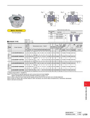
Fig. 1 DCSFMS Fig. 2 DCSFMS
DCON DCON KWW KWW
KAPR KAPR DAH DCCB DCCB DC DC Metric Standard Right hand tool holder only.
| Cutter Diameter | Set Bolt | Geometry | ||
| For inch arbors | DC |
| &80 | HSC12035H | z | x | |
| 100 | HSC16040H | z | ||
| &125 | MBA20040H | x |
KAPR :90° y ARBOR TYPE GAMP :+14°─ 15° GAMF :+21°─ +26° Max.
Dimensions (mm) [inch]
| RE | Order Number | WT | APMX | Spindle | (Fig. |
| (kg) | (mm) | Speed |
| R | DC LF DCON CBDP DAH DCSFMS KWW L8 DCCB | (min -1) | Insert | Anti-seize | Insert |
| Screw Wrench | Lubricant |
| AXD4000R08005CA | s | 5 80 50 25.4[1.0"] 26 13 60 9.5 6 20 1.0 15.5 27000 1 TS3SB TKY08D MK1KS | |||
| 0.4 | |||||
| AXD4000R10006DA | 6 100 63 31.75 | ||||
| s | [1.25"] 32 17 70 12.7 8 26 2.0 15.5 23000 1 TS3SB TKY08D MK1KS | ||||
| 3.2 | |||||
| AXD4000R12507EA | 7 125 63 38.1 | 90 15.9 10 56 2.8 15.5 20000 2 TS3SB TKY08D MK1KS ─ | |||
| s | [1.5"] 40 | ||||
| XDGX1750pp | |||||
| AXD4000R08005CB | 5 80 50 25.4 | PDpR-pp |
s [1.0"] 26 13 60 9.5 6 20 1.0 14.8 27000 1 TS3SB TKY08D MK1KS 4.0 AXD4000R10006DB 6 100 63 31.75 s [1.25"] 32 17 70 12.7 8 26 2.0 14.8 23000 1 TS3SB TKY08D MK1KS
5.0
AXD4000R12507EB 7 125 63 38.1 ─ 90 15.9 10 56 2.8 14.8 20000 2 TS3SB TKY08D MK1KS
s [1.5"] 40 Clamp Torque (lbf-in) : TS3SB=13 Note 1) The maximum spindle speeds are set to ensure tool and insert stability. Before operating this tool read the operation guidance on page L174.
Note 2) When using the tool at high spindle speeds, ensure that the tool and arbor are correctly balanced. Note 3) Note for inserts with a corner radius of .063" and above, as corner radius increases the LF dimension decreases. Note 4) Set bolt not included.