Общий каталог Mitsubishi 2020 - 2021 - страница 684
Навигация
 Каталог Mitsubishi Materials запасные части
 Каталог Mitsubishi Materials резьбонарезной инструмент
 Каталог Mitsubishi Materials СНП с CBN и PCD для токарной обработки
 Каталог Mitsubishi Materials сверлильные инструменты
 Каталог Mitsubishi Materials расточной инструмент
 Каталог Mitsubishi Materials пластины для точения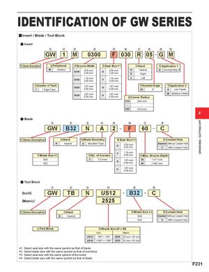
IDENTIFICATION OF GW SERIES
y Insert / Blade / Tool Block
a Insert
GWz 1x Mc 0300v Fb 030n Rm 05, G. M/
| Series Description | cPeripheral | Groove Width | Seat Size*1 | Hand | Application 1 |
| z | v | b | m | . |
| Sintered M | .079 inch | .079 inch | N | Neutral | Grooving/Cutting Off G | |||
| 0200 | 2.00 mm | D | 2.00 mm | |||||
| R | Right | |||||||
| .118 inch | .118 inch | L | Left | |||||
| 0300 | 3.00 mm | F | 3.00 mm | |||||
| xNumber of Teeth | .157 inch | .157 inch | ,Handed Angle | /Application 2 | ||||
| 0400 | 4.00 mm | G | 4.00 mm | |||||
| 1 | 1 Edge Type | 05 | 5° S | Low Feeds | ||||
| .197 inch | .197 inch | M | Medium Feeds | |||||
| 0500 | 5.00 mm | H | 5.00 mm |
nCorner Radius 010 .004 inch 040 .016 inch F
a Blade
GWz B32x Nc Av 2b Fn 60m C,
| Series Description | cHand | vBlade Geometry | Seat Size*3 | ,Coolant Hole |
| z | n |
| A Neutral N Standard Type | Without Coolant Hole Standard .079 inch | |
| D | 2.00 mm | |
| With Coolant Hole C | ||
| * | F | .118 inch |
| 2 xBlade Size bNo. of Corners | mMax. Groove Depth 3.00 mm | |
| B26 2 | 2 Corner | 1.417 inch 36 .157 inch |
| G | 4.00 mm | |
| B32 | 2.362 inch 60 | |
| H | .197 inch | |
| 5.00 mm | ||
| a Tool Block | ||
| Nc TBx GWz | US12v | Cn B32b |
| (Inch) | ||
| (Metric) | 2525 | |
| cHand zSeries Description | nCoolant Hole bBlade Size*4 | |
| Neutral N | Standard Without Coolant Hole B26 | |
| With Coolant Hole C B32 | ||
| xTool Block | vShank Size (H x W) | |
| Inch | Metric | |
| US12 | .750"×.750" 2020 | 20 mm×20 mm |
| US16 | 1.000"×1.000" 2525 | 25 mm×25 mm |
*1 Select seat size with the same symbol as that of blade. *2 Select blade size with the same symbol as that of tool block. *3 Select seat size with the same symbol of the insert. *4 Select blade size with the same symbol as that of blade.