Общий каталог Mitsubishi 2020 - 2021 - страница 1729
Навигация
 Каталог Mitsubishi Materials запасные части
 Каталог Mitsubishi Materials резьбонарезной инструмент
 Каталог Mitsubishi Materials СНП с CBN и PCD для токарной обработки
 Каталог Mitsubishi Materials сверлильные инструменты
 Каталог Mitsubishi Materials расточной инструмент
 Каталог Mitsubishi Materials пластины для точения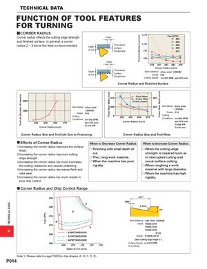
y CORNER RADIUS
1.575 Feed (IPR) Corner radius effects the cutting edge strength Feed
and finished surface. In general, a corner
| radius 2 ― 3 times the feed is recommended. | Theoretical | 1.181 | |
| Depth | Surface | ||
| of Cut | Roughness | .787 |
.394 Feed Corner Radius (inch) Theoretical
Depth Work Material : Alloy steel (200HB) of Cut Surface Grade : P20 Roughness Cutting Speed : vc=395 SFM ap=.020 inch
Corner Radius and Finished Surface
Flank Wear Crater Wear (Crater Depth)
| Work Material : Alloy steel | Work Material : Alloy steel | |||
| (280HB) | (200HB) | |||
| Grade : P10 | Grade : P10 | |||
| Cutting | Cutting | |||
| Conditions : vc=330 SFM | Conditions : vc=460 SFM | |||
| ap=.079 inch | Corner Radius (inch) | ap=.079 inch | ||
| f=.013 IPR | f=.008 IPR | |||
| Corner Radius (inch) | Tc=10 min | |||
| Corner Radius Size and Tool Life Due to Fracturing | Corner Radius Size and Tool Wear |
| a Effects of Corner Radius | When to Decrease Corner Radius | When to Increase Corner Radius | ||
| 1. Increasing the corner radius improves the surface | ||||
| u Finishing with small depth of | u When the cutting edge | |||
| finish. | ||||
| 2. Increasing the corner radius improves cutting | cut. | strength is required such as | ||
| edge strength. | u Thin, long work material. | in interrupted cutting and | ||
| 3. Increasing the corner radius too much increases | u When the machine has poor | uncut surface cutting. | ||
| the cutting resistance and causes chattering. | rigidity. | u When roughing a work |
4. Increasing the corner radius decreases flank and material with large diameter. rake wear. u When the machine has high 5. Increasing the corner radius too much results in rigidity. poor chip control.
a Corner Radius and Chip Control Range
R.039"
P
Depth of Cut (inch) Note 1) Please refer to page P008 for chip shapes (A, B, C, D, E).
Work Material : AISI 1045 (180HB) Insert : TNGG331R TNGG332R TNGG333R (P10) Holder : ETJNR33K16 (Side Cutting Edge angle 3°) Cutting Speed : vc=330 SFM Dry Cutting