Общий каталог Mitsubishi 2020 - 2021 - страница 1693
Навигация
 Каталог Mitsubishi Materials запасные части
 Каталог Mitsubishi Materials резьбонарезной инструмент
 Каталог Mitsubishi Materials СНП с CBN и PCD для токарной обработки
 Каталог Mitsubishi Materials сверлильные инструменты
 Каталог Mitsubishi Materials расточной инструмент
 Каталог Mitsubishi Materials пластины для точения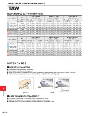
RECOMMENDED CUTTING CONDITIONS
| Work Material | DC | &.5625" &14.0─ | ─&.6094" &15.4mm | &.6250" &15.5─ | ─&.7188" &18.4mm | &.7344" &18.5─ | ─&.8438" &21.4mm |
| Hardness Conditions | Cutting Speed vc(SFM) | Feedfr (IPR) | Cutting Speed vc(SFM) | Feedfr (IPR) | Cutting Speed vc(SFM) | Feedfr (IPR) | |
| P Mild Steel | 230 (195─295) | .008 (.006─.010) | 260 (195─330) | .010 (.008─.012) | 295 (230─360) | .010 (.008─.012) | |
| Carbon Steel | 180─280HB | 230 (195─295) | .008 (.006─.010) | 260 (195─330) | .010 (.008─.012) | 260 (195─330) | .010 (.008─.012) |
| Alloy Steel | 280─350HB | 195 (165─260) | .006 (.005─.007) | 230 (165─295) | .008 (.006─.010) | 230 (165─295) | .008 (.006─.010) |
| M Stainless Steel | 165 (130─195) | .006 (.005─.007) | 165 (130─195) | .006 (.005─.007) | 195 (165─230) | .008 (.006─.009) | |
| K Gray Cast Iron | Tensile Strength | 230 (165─295) | .008 (.006─.010) | 330 (195─395) | .010 (.008─.012) | 390 (195─460) | .010 (.008─.012) |
| Ductile Cast Iron | Tensile Strength | 230 (165─295) | .008 (.006─.010) | 260 (195─295) | .010 (.008─.012) | 260 (195─295) | .010 (.008─.012) |
| Work Material | DC | &.8594" &21.5─ | ─&.9531" &24.4mm | &.9688"─ &24.5─ | &1.0781" &27.4mm | &1.0938" &27.5─ | ─&1.1875" &30.4mm |
| Hardness Conditions | Cutting Speed vc(SFM) | Feedfr (IPR) | Cutting Speed vc(SFM) | Feedfr (IPR) | Cutting Speed vc(SFM) | Feedfr (IPR) | |
| P Mild Steel | 330 (260─390) | .012 (.010─.014) | 360 (260─390) | .012 (.010─.014) | 360 (260─390) | .012 (.010─.014) | |
| Carbon Steel | 180─280HB | 295 (230─360) | .012 (.010─.014) | 330 (260─390) | .012 (.010─.014) | 330 (260─390) | .012 (.010─.014) |
| Alloy Steel | 280─350HB | 260 (195─330) | .010 (.008─.012) | 295 (230─360) | .010 (.008─.012) | 295 (230─360) | .010 (.008─.012) |
| M Stainless Steel | 195 (165─230) | .008 (.006─.009) | 230 (195─260) | .010 (.008─.011) | 230 (195─260) | .010 (.008─.011) | |
| K Gray Cast Iron | Tensile Strength | 425 (260─490) | .014 (.010─.016) | 460 (295─525) | .014 (.010─.016) | 460 (295─525) | .016 (.012─.018) |
| Ductile Cast Iron | Tensile Strength | 295 (195─330) | .012 (.010─.014) | 330 (260─360) | .012 (.010─.014) | 330 (260─360) | .012 (.010─.014) |
NOTES ON USE
yINSERT INSTALLATION
a Loosen insert screw of holder to install insert. a Mesh the insert serration to holder grooves. a Fasten the insert screw using the provided wrench while holding rake face of the insert lightly with your thumb. (Figure 1) a Check that there is no clearance between the insert bottom and holder flute end. (Figure 2)
Slit
OK NG
M
Clearance
Figure 1 Figure 2
yNOTE ON INSERT REPLACEMENT
a Clean insert guide grooves by blowing air before installing a new insert. a Clean the “slit” underneath the insert on the holder with the provided plate. a Use the provided anti-seize lubricant for lubricating the threads of the insert screw.