Общий каталог Mitsubishi 2020 - 2021 - страница 1280
Навигация
 Каталог Mitsubishi Materials запасные части
 Каталог Mitsubishi Materials резьбонарезной инструмент
 Каталог Mitsubishi Materials СНП с CBN и PCD для токарной обработки
 Каталог Mitsubishi Materials сверлильные инструменты
 Каталог Mitsubishi Materials расточной инструмент
 Каталог Mitsubishi Materials пластины для точения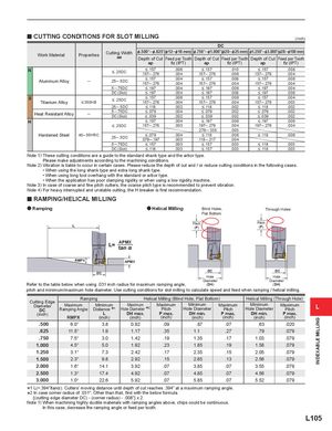
y CUTTING CONDITIONS FOR SLOT MILLING
(inch)
| D | C | |||||||
| Work Material | Properties | Cutting Width | &.500"─&.625"( | &12─&16 mm) | &.750"─&1.000 | "(&20─&25 mm) | &1.250"─&3.000 | "(&28─&100 mm) |
| ae | Depth of Cut | Feed per Tooth | Depth of Cut | Feed per Tooth | Depth of Cut | Feed per Tooth | ||
| ap | fz(IPT) | ap | fz(IPT) | ap | fz(IPT) | |||
| N | .006 | .010 | .008 | |||||
| . | .157─.276 | .004 | .157─.276 | .006 | .157─.276 | .004 | ||
| Ali All | 255DC | .004 | .008 | .008 | ||||
| umnum oy | ─ | .─. | .157─.276 | .004 | .157─.276 | .004 | .157─.276 | .004 |
| .5─.75DC | .004 | .006 | .004 | |||||
| DC(Slot) | .004 | .008 | .006 | |||||
| S | .006 | .006 | .004 | |||||
| Titanium Alloy | . | .157─.276 | .004 | .157─.276 | .004 | .157─.276 | .003 | |
| .25─.5DC | .002 | .002 | .002 | |||||
| .5─.75DC | .004 | .002 | .002 | |||||
| Heat Resistant Alloy | ─ | DC(Slot) | .002 | .002 | .002 | |||
| H | .004 | .006 | .006 | |||||
| .157─.276 | .003 | .197─.276 | .004 | .197─.276 | .004 | |||
| .276─.335 | .003 | |||||||
| Hardened Steel | 40─55HRC | 2DC | .004 | .006 | .006 | |||
| .5─.5 | .079─.197 | .003 | .118─.217 | .004 | ||||
| .5─.75DC | .003 | .003 | .003 | |||||
| DC(Slot) | .003 | .003 | .003 |
Note 1) These cutting conditions are a guide to the standard shank type and the arbor type. Please make adjustments according to the machining conditions. Note 2) Vibration is liable to occur in certain cases. Please reduce the depth of cut and / or reduce cutting conditions in the following cases.
- When using the long shank type and extra long shank type.
- When using long tool overhang with the standard or arbor type.
- When the application has poor clamping rigidity or when using a low rigidity machine.
Note 3) In case of coarse and fine pitch cutters, the coarse pitch type is recommended to prevent vibration. Note 4) For heavy interrupted and unstable cutting, the H breaker is first recommendation.
y RAMPING/HELICAL MILLING
a Ramping a Helical Milling Blind Holes, Through Holes
Flat Bottom Pitch Pitch (P) (P) APMX
RMPX APMX
| DC | DC | DC | ||
| Hole | Hole | |||
| Diameter | Diameter | |||
| Refer to the table below when using .031 inch radius for maximum ramping angle, | (DH) | (DH) |
pitch and minimum/maximum hole diameter. Use cutting conditions for slot milling to calculate speed and feed when ramping / helical milling.
| Ci E | Ram | ping | Helic | al Milling (Blin | d Hole,Flat Botto | m) | Helical Milling ( | Through Hole) |
| Diameter DC (inch) | Maximum Ramping Angle RMPX | Minimum Distance 1 L (inch) | Maximum Hole Diameter 2 DH max. (inch) | Maximum Pitch P max. (inch) | Minimum Hole Diameter DH min. (inch) | Maximum Pitch P max. (inch) | Minimum Hole Diameter DH min. (inch) | Maximum Pitch P max. (inch) |
| .500 | 6.0° | 3.8 | 0.92 | .09 | .87 | .07 | .63 | .020 |
| .625 | 11.5° | 1.9 | 1.17 | .35 | 1.1 | .27 | .79 | .079 |
| .750 | 7.5° | 3.0 | 1.42 | .19 | 1.35 | .17 | 1.03 | .079 |
| 1.000 | 4.5° | 5.0 | 1.92 | .23 | 1.85 | .19 | 1.58 | .079 |
| 1.250 | 3.1° | 7.3 | 2.42 | .17 | 2.35 | .15 | 2.05 | .079 |
| 1.500 | 2.3° | 9.8 | 2.92 | .15 | 2.85 | .13 | 2.56 | .079 |
| 2.000 | 1.6° | 14.1 | 3.92 | .07 | 3.85 | .07 | 3.55 | .079 |
| 2.500 | 1.3° | 17.4 | 4.92 | .07 | 4.85 | .07 | 4.56 | .079 |
| 3.000 | 1.0° | 22.6 | 5.92 | .07 | 5.85 | .07 | 5.52 | .079 |
*1 L(=.394"/tan%). Cutters' moving distance until depth of cut reaches .394" at a maximum ramping angle. *2 In case corner radius of .031". Other than that, find with the below formula. {(cutting edge diameter DC) - (corner radius) - .008"} x 2 Note 1) When machining highly ductile materials with ramping angles above, chips could be continuous. In this case, decrease the ramping angle or feed per tooth.