Общий каталог Mitsubishi 2020 - 2021 - страница 1209
Навигация
 Каталог Mitsubishi Materials запасные части
 Каталог Mitsubishi Materials резьбонарезной инструмент
 Каталог Mitsubishi Materials СНП с CBN и PCD для токарной обработки
 Каталог Mitsubishi Materials сверлильные инструменты
 Каталог Mitsubishi Materials расточной инструмент
 Каталог Mitsubishi Materials пластины для точения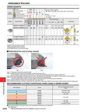
WIPER INSERTS
| P Steel | Cutting Conditions (Guide) : | ||
| M Stainless Steel | : Stable Cutting : General Cutting : Unstable Cutting | ||
| Work | K Cast Iron | ||
| Material | N Non-ferrous Metal | ||
| Honing : | |||
| S Heat-resistant Alloy, Titanium Alloy | E : Round F : Sharp | ||
| H Hardened Steel | T : Chamfer | ||
| Coated Cermet Coated Carbide CBN PCD | Dimensions(inch) | ||
| Cermet | |||
| Shape | Order Number | Geometry |
| L | LE W1 | S | BS RE | |
| MC5020 VP15TF NX2525 |
| WEEW13T3AGER8C | E E | a a | a | .654 | ─ | .649 .156 .295 .059 | AN | ||
| 20° | |||||||||
| WEEW13T3AGTR8C | E T | a | a | .654 | ─ | .649 .156 .295 .059 |
BS RE W1 S
| NP-WEEW13T3AGFR3C | E F | .654 .071 .649 .156 .118 .059 | ||
| a | ||||
| NP-WEEW13T3AGTR3C | E T | a | .654 .071 .649 .156 .118 .059 |
BS RE W1 S *Wiper inserts are single-cornered. *CBN grade MB710 is for cast iron.
*PCD grade MD220 is for aluminum alloy.
yInstructions for use of wiper inserts
AS 29°
AS 29°
Fig.1 Fig.2 Note 1) These wiper inserts are single-cornered. Note 2) Install the insert so that the cutting edge is located as shown in Fig. 1. Do not install the wiper insert as shown in Fig. 2. (The insert may be damaged by a too heavy cutting load.) Note 3) Recommended depth of cutting is ap=.008"-.020". (Be aware of the cutting load if the depth of cut is over the recommendation.) Note 4) The major cutting edge of a wiper insert is set more inside than a general tooth. L This is to prevent heavy loads on the wiper insert. (To prevent fracture set the feed under .008 inch/t.) Note 5) Excellent finished surface can be obtained with one wiper insert. Note 6) When the feed per revolution is larger than the width of the wiper edge, install 2 or more wiper inserts equally inside the cutting body.
RECOMMENDED CUTTING CONDITIONS WHEN USING A WIPER INSERT
| Work Material | Grade | Recommended Cutting Speed (SFM) |
| VP25N | 655(260─820) | |
| P | VP15TF | 590(260─820) |
| M | VP15TF | 390─885 |
| MC5020 | ||
| K | VP15TF | 425─820 |
| MB710 | ||
| S | VP15TF | 65─165 |
| H | VP15TF | 130─260 |
| N | MD220 | 2130(985─3280) |
aRecommended depth of cut (ap) is .008"-.020" and feed per tooth (fz) is up to .008 inch/t. L034 <CBN and PCD wiper inserts are available in 1 piece in one case>