Основной каталог Kyocera 2021 - 2022 - страница 901
Навигация
 Каталог Kyocera пластины с CVD покрытием для обработки чугуна
 Каталог Kyocera пластины TQ для нарезания резьбы c прессованным стружколомом
 Каталог Kyocera высокопроизводительные модульные сверла DRA
 Каталог Kyocera фрезы MRX с позитивными круглыми пластинами
 Каталог Kyocera пластины с CVD покрытием для обработки стали
 - Cover
- Chapter Overview
- Contents
- Introduction
- Introduction
- Negative-Chipbreaker
- Positive-Chipbreaker
- Page Guide
- Cermet / coated carbide / carbide lineup
- Negative inserts 80° Rhombic
- 55° Rhombic
- 55° Parallelogramm
- Round
- 90° Square
- 90° Square
- 60° Triangle
- 35° Rhombic
- 80° Trigon
- Small double sided tools
- 80° Rhombic
- 55° Rhombic
- 55° Rhombic
- 70° Rhombic
- Round
- 90° Square
- 90° Square
- 60° Triangle
- 60° Triangle
- 35° Rhombic
- 35° Rhombic
- 80° Trigon
- Bearing machining Round / Square-Type
- Inserts for back turning TKFB
- ABS / ABW
- Ceramic lineup
- Negative inserts 80° Rhombic
- 55° Rhombic
- 75° Rhombic
- Round
- 90° Square
- 60° Triangle
- 35° Rhombic
- Positive inserts Round
- Square
- Triangle
- Inserts for high hardened roll
- Grooving inserts
- CBN Lineup
- Introduction
- Solid bar EZB-NB
- GMN
- GDGS
- Grooving inserts GBA
- 80° Trigon
- 35° Rhombic
- 60° Triangle
- 55° Rhombic
- Positive inserts 80° Rhombic
- 60° Triangle / Solid
- 90° Square / Solid
- Round / Solid
- 80° Rhombic / Solid
- 80° Trigon
- 35° Rhombic
- 60° Triangle
- 90° Square
- 55° Rhombic
- Negative inserts 80° Rhombic
- PCD Lineup
- Introduction
- Milling inserts Available inserts
- VNBR-NB
- VNGR-NB
- Solid bar EZB-NB
- TKF
- GMGW
- GMN
- GDGS
- GV/GVF
- Grooving inserts GBA/TGF
- 80° Trigon
- 35° Rhombic
- 60° Triangle
- 90° Square
- 55° Rhombic
- Positive inserts 80° Rhombic
- 80° Trigon
- 35° Rhombic
- 60° Triangle
- 55° Rhombic
- Negative inserts 80° Rhombic
- Introduction
- Toolholders for general purpose
- CN insert DCLN/DCLN-JCT/PCLN
- DN insert DDJN/DDJN-JCT/DDHN
- PDJN/PDHN
- SN insert DSBN/PSBN/PSKN
- PSSN/PSDN
- TN insert DTGN/PTGN/PTFN
- WTJN/WTKN/WTEN
- VN insert DVLN/DVPN/DVVN
- MVLN/MVVN
- PVLN/PVPN/PVVN
- RC insert PRGC/PRXC
- RN insert PRGN
- WN Insert DWLN/DWLN-JCT/PWLN/WWLN
- Toolholders for ceramic inserts
- Selection guide for ceramic inserts
- RN insert CRSN/CRDN
- SN insert CSRN/CS-N/CSKN/CSYN/CSSN/CSDN
- EN insert CELN
- DN insert CDJN
- CN insert CCLN
- TN insert CTJN/CTUN
- Toolholders for CBN inserts
- CNMN insert CCRN-A/CCLN-A
- RNMN insert CRSN-A/CRDN-A
- SNMN insert CSRN-A/CSKN-A/CSSN-A/CSDN-A
- TNMN insert CTJN-A/CTUN-A
- Toolholders for bearing machining
- RCMT insert PRGC-BE
- SNMF insert CBSN
- Recommended cutting conditions
- Introduction
- Toolholders for back turning
- TKFB insert TKFB
- KTKF / KTKF Goose-neck holder
- ABS15 insert AABS-40F/SABS-40F
- ABW15 insert AABW-40F/SABW-40F
- ABW23 insert AABW-50F/SABW-50F
- Goose-neck toolholders
- DC insert SDJC
- VP insert SVLP
- External toolholders
- CC insert ACLC-FF
- SCLC
- SCLC-FF/SCLC-FFJCT
- DC insert ADJC-FF
- SDJC-FF
- SDJC-FFJCT
- SDJC
- SDLC-FF
- SDXC
- SDNC-F
- SDNC
- DP insert SDLP-FF
- TC/TP insert STGC
- STGP
- VB/VC insert AVJB-FF/SVJB-FF/SVJB-FFJCT/SVJB/SVPB/SVVB
- SVJC-FF/SVLC-FF
- SVPC-FF/SVVC
- VP insert SVJP-FF/SVJP-FFJCT/SVLP-FF/SVPP-FF
- External sleeve holders
- CC insert S...SCLC
- DC insert S...SDUC/S...SDLC
- VB/VC insert S...SVUB/S...SVUC
- Toolholders for small double sided tooling
- CN insert SCLN-FF (without offset)
- DN insert SDLN-FF (without offset)
- TN insert STLN-FF (without offset)
- Toolholders for double sided tooling for automatic lathes
- CN insert PCLN-FF (without offset)
- TN insert PTLN-FF (without offset)
- Recommended cutting conditions
- Introduction
- Solid tip bars for micro boring
- System Tip-Bars VNB type
- VNBX-S
- TWB
- STW/S-STW
- TWBT
- Dynamic-Bars
- CC insert A/S-SCLC-AE
- CP insert A-SCLP-AE
- DC insert A-SDUC-AE
- JC insert C-SJLC
- TC insert A-STLC-AE
- TB/TP insert S-STLB-AE
- VB/VC/VP insert A-SVJP-AE/A-SVJC-AE/A-SVJB-AE
- WB/WP insert S-SWUB-AE/A-SWUP-AE
- Borings bars (screw clamp / top clamp)
- SP insert S-SSKP/S-CSKP
- TP insert S-CTUP
- Bearing machining
- RPMT insert SRCP-B
- SNMF insert CBSN-B
- AD Bars
- CN insert HA-PCLN
- DN insert HA-PDUN
- TN insert HA-PTFN
- CC insert HA-SCLC
- DC insert HA-SDUC
- Boring adapter for AD Bars AD type with dampener system
- Boring bars for negative type inserts
- CN insert A-DCLN
- DN insert S-PDUN/A-PDUN (11)
- SN insert A-DSKN
- TN insert A-DTFN
- WN insert S-PWLN/A-PWLN
- Boring bars for ceramic inserts
- Boring bars for CBN inserts
- Technical information
- Applicable sleeves
- Introduction
- External grooving
- GBA type GBA
- KGB/KGBS
- GBF-KGBF-JCT
- TGF type TGF
- S-KGBF
- KTGF-F/KTGF/S-KTGF
- KGD
- KGD-JCT (Integral type)
- KGD (Integral type for automatic lathes)
- KGD (Integral type)
- KGDF S separate type
- GMGW type GMGW
- GH/GHU/GA type GH/GHU/GA
- GM/GMN/GMM/GMG/GMGA/FGG type GM/GMN/GMM/GMG/GMGA/FGG
- Internal grooving
- KGIA
- GIA type GIA
- GMM/GMG/GMGA type GMM/GMG/GMGA
- GH/GHU type GH/GHU
- GBA type KIGBA
- GDM type GDM
- GV type GV
- SIGE-WH-90 carbide shank bar (for automatic lathe; with coolant hole)
- SIGE-WH carbide shank bar (with coolant hole)
- SIGE-EH Excellent Bar (with coolant hole)
- GE/GER type GE/GER
- GC type GC
- VNG type VNG
- GMM
- Face grooving
- KGDF-Z (Integral type)
- GDFM/GDFMS type GDFM/GDMFS
- TWFG/TWFGT small diameter face grooving (Twin-Bars) TWFG
- VNFG type VNFG
- KGDF 0° separate type
- KGDF 90 separate type
- FTK type FTK
- GMM/GMG/GMGA type GMM/GMG/GMGA
- FMM/FMN type FMM/FMN
- GIFV (A/B/C)
- GFV\AA
- GVF type GVF
- Grooving
- Introduction
- Small diameter cut-off
- TKF type TKF
- KTKF
- KTKF-JCT
- KTKFS
- TKFS type TKFS
- KTKF-S
- KGD type
- GDM/GDMS/GDG type GDM/GDMS/GDG
- KGD (Integral type for automatic lathe)
- KGDS (for sub spindle tooling)
- KGD-JCT (Integral type)
- KGD (Integral type)
- KGD-JCT (Integral type for automatic lathe)
- KGD-JCT
- KGDS separate type
- KGM type
- GMM/GMN/GMR/GML type GMM/GMN/GMR/GMLw
- KGM/KGM-T/KGMM/KGMS
- 1-edge cut-off inserts
- TKN/TK type TKN/TK
- KTKB-SS/KTKB-S
- Toolblocks
- KTKH-S (Integral type)
- Introduction
- Threading inserts
- Metric External threading / 60° full profile
- Internal threading / 60° full profile
- Unified External threading / 60° full profile
- Internal threading / 60° full profile
- Parallel pipe, Whitworth External threading
- Internal threading
- Tapered pipe External threading / 55° full profile
- Internal threading / 55° full profile
- American national tapered pipe External threading
- Internal threading
- 60° type (Partial profile/M, UN) External threading
- Internal threading
- 55° type (Partial profile/G, R, Rc, W) External threading
- Internal threading
- 30° type (Trapezoidal) External threading
- Internal threading
- Threading toolholders
- External toolholders KTN/KTNS/KTN-JCT
- S-KTN
- Internal toolholders SIN/CIN
- Multipurpose threading tools
- TKFT for small parts machining TKFT
- KTKF
- TTX for small parts machining TTX
- KTTX/S-KTTX
- TT for external and internal threading TT
- KTT (external)
- KITG (internal)
- System Bar for micro internal threading VNT
- TPGB for internal threading TPGB
- S-STWP/S-STWP-E
- Recommended cutting conditions
- Depth of cut and number of passes
- Applicable toolholders and inserts
- Threading methods
- Threading methods and basic profiles
- Thread types
- Introduction
- MagicDrill DRA
- SF-DRA 12 DC
- SF-DRA 8 DC
- SF-DRA 5 DC
- SF-DRA 3 DC
- Flanged shank SF SF-DRA 1.5 DC
- Chamfering attachment for SS-DRA CH\-DRA
- SS-DRA 8 DC
- SS-DRA 5 DC
- SS-DRA 3 DC
- Straight shank SS SS-DRA 1.5 DC
- Recommended cutting conditions
- MagicDrill DRC
- Straight shank SS SS-DRC 3 DC
- SS-DRC 5 DC
- SS-DRC 8 DC
- Chamfering attachment for SS-DRC CH\-DRC
- Flanged shank SF SF-DRC 3 DC
- SF-DRC 5 DC
- SF-DRC 8 DC
- Recommended cutting conditions
- MagicDrill DRV
- Chamfering attachment for DRV CH\-DRV
- DRV 6 DC
- DRV 5 DC
- DRV 4 DC
- DRV 3 DC
- Toolholder DRV DRV 2 DC
- Recommended cutting conditions
- Adjustable sleeve (DRV/DRZ/DRX)
- MagicDrill DRZ
- Toolholder DRZ DRZ 2 DC
- DRZ 3 DC
- DRZ-CR
- Recommended cutting conditions
- MagicDrill DRS
- MagicDrill DRX
- Trouble shooting (DRV / DRX / DRZ / DRX)
- Lathe installation DRX/DRZ
- MagicDrill DRW
- Introduction
- Introduction
- ISO identification
- MFPN Series MFPN66
- MFK / MFK-SF
- MOF45 OFMT
- Lead angle 15°
- MSRS15 SPMT
- Lead angle 0°/ 2°
- MEW LOMU/LOGT
- MEC/MECX BDGT/BDMT
- MEWH LOMU/LOGT
- MEV TOMT
- MECH/MECHT BDMT
- MECH/MECHT MECHT
- MFWN WNEU/WNMU/WNGT
- MFSN88 SNMU
- MFLN90 LOGU
- MSRS90 SPMT
- MSR / MSR-BT50 APMT
- DMC/DMC-SX/DMC-H NDCT/NDCW/NDMM
- MFAH ENET
- MEAS KCGT
- High feed cutter
- MFH Series SOMT/LOGU/LPGT
- MFH Series MFH Mini
- MFH Series MFH Micro
- Multi-Function end mill
- Applicable inserts GOMT/JOMT
- Slott mill
- Ball-nose / radius type cutters
- MRF/MRFW RDFG
- MRW ROMU
- MRX RDMT/RDGT/RPMT/RPGT
- Other applications
- MCSE (chamfering end mill)
- Square-type inserts MEF (bolt countersink end mill)
- S type inserts METS (T-Slot mill)
- MVG (ring grooving end milll for M/C)
- GVR/GVFR
- MGI (grooving end mill for M/C)
- Grooving GVR/GVFR
- Other inserts
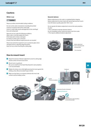
Lead angle 0°/ 2° MFAH Cautions While in use Dynamic balance Caution Balance adjustment on the cutter is completed before shipping Balance adjustment has been made with special high precision inserts Please use within recommended cutting conditions to be ISO balance quality grade (ISO 1940-1) G2.5 Do not run the cutter at revolutions exceeding the printed Do not operate the balance adjustment screw at the outer periphery maximum revolution limit of the cutter body of cutter Inserts or cutter body may be damaged due to the centrifugal ➮ This could lead to improper dynamic balance force and cutting load Do not completely remove clamp and clamp screw from cutter Please do not use under the following conditions: ➮ This requires additional balance adjustment When cutter is not fully loaded with inserts If the body and/or clamp is damaged If a clamp or clamp screw is removed If inserts that have different regrind amounts are mounted Please wear protective equipment such as protective glove when changing inserts or adjusting edge fluctuation Balance adjustment Injury can occur when touching the cutting edge screw is mounted at the necessary point * Do not operate How to mount insert 1 Adjust the clearance between adjustment screw for cutting edge and the surface of insert to be 0.5mm 2 Mount insert on guide pin (Be sure to install from the head. Mounting from outer peripheryis not recommended) M 3 Tighten the clamp screw while lightly pressing the insert against the Guide pin holding surface (Recommended Torque 4.2N•m) 4 Make sure that there is no clearance between the insert side surfaces and the holding surface 0.5mm * Per one revolution Loosening (Counter-clockwise) Tightening (Clockwise) *Caution Mounting from outer periphery is not recommended M129 Milling