Основной каталог Kyocera 2021 - 2022 - страница 737
Навигация
 Каталог Kyocera пластины с CVD покрытием для обработки чугуна
 Каталог Kyocera пластины TQ для нарезания резьбы c прессованным стружколомом
 Каталог Kyocera высокопроизводительные модульные сверла DRA
 Каталог Kyocera фрезы MRX с позитивными круглыми пластинами
 Каталог Kyocera пластины с CVD покрытием для обработки стали
 - Cover
- Chapter Overview
- Contents
- Introduction
- Introduction
- Negative-Chipbreaker
- Positive-Chipbreaker
- Page Guide
- Cermet / coated carbide / carbide lineup
- Negative inserts 80° Rhombic
- 55° Rhombic
- 55° Parallelogramm
- Round
- 90° Square
- 90° Square
- 60° Triangle
- 35° Rhombic
- 80° Trigon
- Small double sided tools
- 80° Rhombic
- 55° Rhombic
- 55° Rhombic
- 70° Rhombic
- Round
- 90° Square
- 90° Square
- 60° Triangle
- 60° Triangle
- 35° Rhombic
- 35° Rhombic
- 80° Trigon
- Bearing machining Round / Square-Type
- Inserts for back turning TKFB
- ABS / ABW
- Ceramic lineup
- Negative inserts 80° Rhombic
- 55° Rhombic
- 75° Rhombic
- Round
- 90° Square
- 60° Triangle
- 35° Rhombic
- Positive inserts Round
- Square
- Triangle
- Inserts for high hardened roll
- Grooving inserts
- CBN Lineup
- Introduction
- Solid bar EZB-NB
- GMN
- GDGS
- Grooving inserts GBA
- 80° Trigon
- 35° Rhombic
- 60° Triangle
- 55° Rhombic
- Positive inserts 80° Rhombic
- 60° Triangle / Solid
- 90° Square / Solid
- Round / Solid
- 80° Rhombic / Solid
- 80° Trigon
- 35° Rhombic
- 60° Triangle
- 90° Square
- 55° Rhombic
- Negative inserts 80° Rhombic
- PCD Lineup
- Introduction
- Milling inserts Available inserts
- VNBR-NB
- VNGR-NB
- Solid bar EZB-NB
- TKF
- GMGW
- GMN
- GDGS
- GV/GVF
- Grooving inserts GBA/TGF
- 80° Trigon
- 35° Rhombic
- 60° Triangle
- 90° Square
- 55° Rhombic
- Positive inserts 80° Rhombic
- 80° Trigon
- 35° Rhombic
- 60° Triangle
- 55° Rhombic
- Negative inserts 80° Rhombic
- Introduction
- Toolholders for general purpose
- CN insert DCLN/DCLN-JCT/PCLN
- DN insert DDJN/DDJN-JCT/DDHN
- PDJN/PDHN
- SN insert DSBN/PSBN/PSKN
- PSSN/PSDN
- TN insert DTGN/PTGN/PTFN
- WTJN/WTKN/WTEN
- VN insert DVLN/DVPN/DVVN
- MVLN/MVVN
- PVLN/PVPN/PVVN
- RC insert PRGC/PRXC
- RN insert PRGN
- WN Insert DWLN/DWLN-JCT/PWLN/WWLN
- Toolholders for ceramic inserts
- Selection guide for ceramic inserts
- RN insert CRSN/CRDN
- SN insert CSRN/CS-N/CSKN/CSYN/CSSN/CSDN
- EN insert CELN
- DN insert CDJN
- CN insert CCLN
- TN insert CTJN/CTUN
- Toolholders for CBN inserts
- CNMN insert CCRN-A/CCLN-A
- RNMN insert CRSN-A/CRDN-A
- SNMN insert CSRN-A/CSKN-A/CSSN-A/CSDN-A
- TNMN insert CTJN-A/CTUN-A
- Toolholders for bearing machining
- RCMT insert PRGC-BE
- SNMF insert CBSN
- Recommended cutting conditions
- Introduction
- Toolholders for back turning
- TKFB insert TKFB
- KTKF / KTKF Goose-neck holder
- ABS15 insert AABS-40F/SABS-40F
- ABW15 insert AABW-40F/SABW-40F
- ABW23 insert AABW-50F/SABW-50F
- Goose-neck toolholders
- DC insert SDJC
- VP insert SVLP
- External toolholders
- CC insert ACLC-FF
- SCLC
- SCLC-FF/SCLC-FFJCT
- DC insert ADJC-FF
- SDJC-FF
- SDJC-FFJCT
- SDJC
- SDLC-FF
- SDXC
- SDNC-F
- SDNC
- DP insert SDLP-FF
- TC/TP insert STGC
- STGP
- VB/VC insert AVJB-FF/SVJB-FF/SVJB-FFJCT/SVJB/SVPB/SVVB
- SVJC-FF/SVLC-FF
- SVPC-FF/SVVC
- VP insert SVJP-FF/SVJP-FFJCT/SVLP-FF/SVPP-FF
- External sleeve holders
- CC insert S...SCLC
- DC insert S...SDUC/S...SDLC
- VB/VC insert S...SVUB/S...SVUC
- Toolholders for small double sided tooling
- CN insert SCLN-FF (without offset)
- DN insert SDLN-FF (without offset)
- TN insert STLN-FF (without offset)
- Toolholders for double sided tooling for automatic lathes
- CN insert PCLN-FF (without offset)
- TN insert PTLN-FF (without offset)
- Recommended cutting conditions
- Introduction
- Solid tip bars for micro boring
- System Tip-Bars VNB type
- VNBX-S
- TWB
- STW/S-STW
- TWBT
- Dynamic-Bars
- CC insert A/S-SCLC-AE
- CP insert A-SCLP-AE
- DC insert A-SDUC-AE
- JC insert C-SJLC
- TC insert A-STLC-AE
- TB/TP insert S-STLB-AE
- VB/VC/VP insert A-SVJP-AE/A-SVJC-AE/A-SVJB-AE
- WB/WP insert S-SWUB-AE/A-SWUP-AE
- Borings bars (screw clamp / top clamp)
- SP insert S-SSKP/S-CSKP
- TP insert S-CTUP
- Bearing machining
- RPMT insert SRCP-B
- SNMF insert CBSN-B
- AD Bars
- CN insert HA-PCLN
- DN insert HA-PDUN
- TN insert HA-PTFN
- CC insert HA-SCLC
- DC insert HA-SDUC
- Boring adapter for AD Bars AD type with dampener system
- Boring bars for negative type inserts
- CN insert A-DCLN
- DN insert S-PDUN/A-PDUN (11)
- SN insert A-DSKN
- TN insert A-DTFN
- WN insert S-PWLN/A-PWLN
- Boring bars for ceramic inserts
- Boring bars for CBN inserts
- Technical information
- Applicable sleeves
- Introduction
- External grooving
- GBA type GBA
- KGB/KGBS
- GBF-KGBF-JCT
- TGF type TGF
- S-KGBF
- KTGF-F/KTGF/S-KTGF
- KGD
- KGD-JCT (Integral type)
- KGD (Integral type for automatic lathes)
- KGD (Integral type)
- KGDF S separate type
- GMGW type GMGW
- GH/GHU/GA type GH/GHU/GA
- GM/GMN/GMM/GMG/GMGA/FGG type GM/GMN/GMM/GMG/GMGA/FGG
- Internal grooving
- KGIA
- GIA type GIA
- GMM/GMG/GMGA type GMM/GMG/GMGA
- GH/GHU type GH/GHU
- GBA type KIGBA
- GDM type GDM
- GV type GV
- SIGE-WH-90 carbide shank bar (for automatic lathe; with coolant hole)
- SIGE-WH carbide shank bar (with coolant hole)
- SIGE-EH Excellent Bar (with coolant hole)
- GE/GER type GE/GER
- GC type GC
- VNG type VNG
- GMM
- Face grooving
- KGDF-Z (Integral type)
- GDFM/GDFMS type GDFM/GDMFS
- TWFG/TWFGT small diameter face grooving (Twin-Bars) TWFG
- VNFG type VNFG
- KGDF 0° separate type
- KGDF 90 separate type
- FTK type FTK
- GMM/GMG/GMGA type GMM/GMG/GMGA
- FMM/FMN type FMM/FMN
- GIFV (A/B/C)
- GFV\AA
- GVF type GVF
- Grooving
- Introduction
- Small diameter cut-off
- TKF type TKF
- KTKF
- KTKF-JCT
- KTKFS
- TKFS type TKFS
- KTKF-S
- KGD type
- GDM/GDMS/GDG type GDM/GDMS/GDG
- KGD (Integral type for automatic lathe)
- KGDS (for sub spindle tooling)
- KGD-JCT (Integral type)
- KGD (Integral type)
- KGD-JCT (Integral type for automatic lathe)
- KGD-JCT
- KGDS separate type
- KGM type
- GMM/GMN/GMR/GML type GMM/GMN/GMR/GMLw
- KGM/KGM-T/KGMM/KGMS
- 1-edge cut-off inserts
- TKN/TK type TKN/TK
- KTKB-SS/KTKB-S
- Toolblocks
- KTKH-S (Integral type)
- Introduction
- Threading inserts
- Metric External threading / 60° full profile
- Internal threading / 60° full profile
- Unified External threading / 60° full profile
- Internal threading / 60° full profile
- Parallel pipe, Whitworth External threading
- Internal threading
- Tapered pipe External threading / 55° full profile
- Internal threading / 55° full profile
- American national tapered pipe External threading
- Internal threading
- 60° type (Partial profile/M, UN) External threading
- Internal threading
- 55° type (Partial profile/G, R, Rc, W) External threading
- Internal threading
- 30° type (Trapezoidal) External threading
- Internal threading
- Threading toolholders
- External toolholders KTN/KTNS/KTN-JCT
- S-KTN
- Internal toolholders SIN/CIN
- Multipurpose threading tools
- TKFT for small parts machining TKFT
- KTKF
- TTX for small parts machining TTX
- KTTX/S-KTTX
- TT for external and internal threading TT
- KTT (external)
- KITG (internal)
- System Bar for micro internal threading VNT
- TPGB for internal threading TPGB
- S-STWP/S-STWP-E
- Recommended cutting conditions
- Depth of cut and number of passes
- Applicable toolholders and inserts
- Threading methods
- Threading methods and basic profiles
- Thread types
- Introduction
- MagicDrill DRA
- SF-DRA 12 DC
- SF-DRA 8 DC
- SF-DRA 5 DC
- SF-DRA 3 DC
- Flanged shank SF SF-DRA 1.5 DC
- Chamfering attachment for SS-DRA CH\-DRA
- SS-DRA 8 DC
- SS-DRA 5 DC
- SS-DRA 3 DC
- Straight shank SS SS-DRA 1.5 DC
- Recommended cutting conditions
- MagicDrill DRC
- Straight shank SS SS-DRC 3 DC
- SS-DRC 5 DC
- SS-DRC 8 DC
- Chamfering attachment for SS-DRC CH\-DRC
- Flanged shank SF SF-DRC 3 DC
- SF-DRC 5 DC
- SF-DRC 8 DC
- Recommended cutting conditions
- MagicDrill DRV
- Chamfering attachment for DRV CH\-DRV
- DRV 6 DC
- DRV 5 DC
- DRV 4 DC
- DRV 3 DC
- Toolholder DRV DRV 2 DC
- Recommended cutting conditions
- Adjustable sleeve (DRV/DRZ/DRX)
- MagicDrill DRZ
- Toolholder DRZ DRZ 2 DC
- DRZ 3 DC
- DRZ-CR
- Recommended cutting conditions
- MagicDrill DRS
- MagicDrill DRX
- Trouble shooting (DRV / DRX / DRZ / DRX)
- Lathe installation DRX/DRZ
- MagicDrill DRW
- Introduction
- Introduction
- ISO identification
- MFPN Series MFPN66
- MFK / MFK-SF
- MOF45 OFMT
- Lead angle 15°
- MSRS15 SPMT
- Lead angle 0°/ 2°
- MEW LOMU/LOGT
- MEC/MECX BDGT/BDMT
- MEWH LOMU/LOGT
- MEV TOMT
- MECH/MECHT BDMT
- MECH/MECHT MECHT
- MFWN WNEU/WNMU/WNGT
- MFSN88 SNMU
- MFLN90 LOGU
- MSRS90 SPMT
- MSR / MSR-BT50 APMT
- DMC/DMC-SX/DMC-H NDCT/NDCW/NDMM
- MFAH ENET
- MEAS KCGT
- High feed cutter
- MFH Series SOMT/LOGU/LPGT
- MFH Series MFH Mini
- MFH Series MFH Micro
- Multi-Function end mill
- Applicable inserts GOMT/JOMT
- Slott mill
- Ball-nose / radius type cutters
- MRF/MRFW RDFG
- MRW ROMU
- MRX RDMT/RDGT/RPMT/RPGT
- Other applications
- MCSE (chamfering end mill)
- Square-type inserts MEF (bolt countersink end mill)
- S type inserts METS (T-Slot mill)
- MVG (ring grooving end milll for M/C)
- GVR/GVFR
- MGI (grooving end mill for M/C)
- Grooving GVR/GVFR
- Other inserts
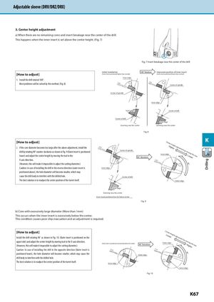
Adjustable sleeve (DRV/DRZ/DRX) SHE type 3. Center height adjustment a) When there are no remaining cores and insert breakage near the center of the drill. This happens when the inner insert is set above the center height. (Fig. 7) Fig. 7 Insert breakage near the center of the drill Initial installation 180˚ Rotation Improved position of inner insert [How to adjust] (Inner insert positioned higher than normal) (Inner insert positioned lower than normal) Inner edge 1. Install the drill rotated 180°. X-axi X-axi of th s Most problems will be solved by this method. (Fig. 8) of th s em ach ine em ach ine Center of spindle Center of spindle Inner edge Inner Inner edge edge Center of drill Center of drill Inner edge Zooming near the center Zooming near the center Fig. 8 [How to adjust] Cen ter hei K ght X-ax Hig adj 2. If the core diameter becomes too large after the above adjustment, install the of th is em her ust me ach ine nt b Center of spindle ym drill by rotating 90° counter-clockwise as shown in Fig. 9 (Outer insert is positioned ovi ng Inner edge the lower) and adjust the center height by moving the tool in the Low too l 90˚ Rotation er X-axis direction. Drilling X-ax of th is em ac hine (However, this will make it impossible to adjust the cutting diameter.) 90 ˚ Caution: In case of installing the drill in the reverse direction (outer insert is Inner edge positioned above), the hole diameter will become smaller, which may cause the drill body to interfere with the drilled hole. Center of drill The best solution is to readjust the center position of the turret itself. Outer edge Inner edge Zooming near the center Inner insert positioned too far below center Fig. 9 b) Core with excessively large diameter (More than 1mm) This occurs when the inner insert is excessively below the center. This condition causes poor chip evacuation and an adjustment is required. Cen [How to adjust] te rh Low eight a er dju Install the drill rotating 90˚ as shown in Fig. 10. (Outer insert is positioned on the stm ent by mo upper side) and adjust the center height by moving tool in the X-axis direction. Outer edge vin gt Hig he too Inner insert is positioned excessively below the center. 90˚ Rotation (However, this will make it impossible to adjust the cutting diameter.) her l Caution: In case of installing the drill in the opposite direction (Outer insert is X-ax X-ax of th is of th is em em achine ach ine 90˚ positioned lower), the hole diameter will become smaller, which may cause the Outer edge drill body to interfere with the drilled hole. The best solution is to readjust the center position of the turret itself. Inner edge Inner edge Fig. 10 K67