Общий каталог Widia 2017 - страница 974
Навигация
 Каталог Widia токарный инструмент 2017
 Каталог Widia трохоидальное фрезерование
 Каталог Widia техническое руководство по разверткам
 Каталог Widia фрезы со сменными пластинами 2016
 Каталог Widia достижения 2020
- Table of Contents
- Turning
- Turning • ISO Inserts
- Turning • Tools for External Turning and Internal Boring
- Turning • Tools for External Turning and Internal Boring
- Turning • Tools for Small Hole Boring
- com E1Turning • Grooving and Cut-Off
- Turning • Threading
- Indexable Milling
- Indexable Milling • Face Mills
- Indexable Milling • Chamfer Mills
- Indexable Milling • 90° Shoulder Mills
- Indexable Milling • Helical Mills
- Indexable Milling • Slotting Mills
- Indexable Milling • Copy Mills
- Solid End Milling
- Solid End Milling • High-Performance Solid Carbide End Mills
- Solid End Milling • General Purpose Solid Carbide End Mills
- Solid End Milling • High-Performance High-Speed Steel (HSS-E/PM)
- Solid End Milling • Burs
- Holemaking
- Holemaking • High-Performance Solid Carbide Drills
- Holemaking • Modular Drills
- Holemaking • Indexable Drills
- Holemaking • Modular Drills
- Holemaking • Indexable Drills
- Holemaking • Hole Finishing
- Tapping
- Tapping Portfolio
- Index by Order Number
- Index by Catalogue Number
- Global Contacts
- Informational Icons Guide
- Material Overview • DIN
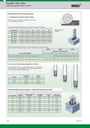
Selecting the Correct Cutting Values
1. fz depends on the Ap1 and ae values
With round inserts, two factors can affect the hm: Ap1 and ae. fz has to be adjusted accordingly.
Recommended Starting Feed Rate Values (fz) Related to the Ap1 and ae Values:
| ae engagement | 10% | 20% | 30% | 40% | 50% | 100% |
| Ap1 = 1mm | 1,52mm | 1,07mm | 0,88mm | 0,76mm | 0,68mm | 0,48mm |
| Ap1 = 2mm | 1,07mm | 0,76mm | 0,62mm | 0,54mm | 0,48mm | 0,34mm |
| Ap1 = 3mm | 0,88mm | 0,62mm | 0,51mm | 0,44mm | 0,39mm | 0,28mm |
| Ap1 = 4mm | 0,76mm | 0,54mm | 0,44mm | 0,38mm | 0,34mm | 0,24mm |
| Ap1 = 5mm | 0,62mm | 0,44mm | 0,36mm | 0,31mm | 0,26mm | 0,20mm |
| Ap1 = 6mm | 0,54mm | 0,38mm | 0,31mm | 0,27mm | 0,24mm | 0,17mm |
Example application highlighted.
Example Cutting Conditions for iC16mm... Insert in Pocketing, up to 3 L/D approximately:
| TN2505 | fee | d per too | TN6525 th fz (m | m)/ae>5 | 0% | TN6540 | |||||
| insert = R | DPX1604M0SN | min | med | max | min | med | max | min | med | max | |
| Edge Geometry MM | ae>50% | Recommended starting Ap1 = 3mm | – | – | – | 0,28mm | 0,45mm | 0,65mm | 0,28mm | 0,50mm | 0,70mm |
| Edge Geometry MH | ae>50% | Recommended starting Ap1 = 3mm | 0,28mm | 0,35mm | 0,50mm | 0,28mm | 0,50mm | 0,75mm | 0,28mm | 0,60mm | 0,80mm |
2. Ap1 and vc corrections depend on L/D ratio
With increasing L/D ratios, or overhang, vibrations can occur due to reduced rigidity. To ensure successful application, it is recommended to adjust Ap1 and vc values according to the following table:
% of Ap1 max % of vc
L/D ratio to reduce to reduce
L
L
D
| L/D ratio | % of Ap1 max to reduce | % of vc to reduce |
| 0% | 0% | |
| 2 | 65–75% | 10–15% |
| >4 | 80–95% | 20–40% |
L
D
Recommended Cutting Conditions • Helical Interpolation from Solid D
| min hole | max hole diameter | Ap1 max per | max ramp | Ap1 max | ||||
| cutter diameter | diameter | (fl at bottom) | revolution | angle | when plunging | Cutter | ||
| Diameter |
32 36mm 48mm 3mm 20° 3mm
| cutter diameter | min hole diameter | max hole diameter (fl at bottom) | Ap1 max per revolution | max ramp angle | Ap1 max whenplunging |
| 32 | 36mm | 48mm | 3mm | 20° | 3mm |
| 50 | 69mm | 84mm | 8mm | 9,5° | 4,8mm |
| 52 | 73mm | 88mm | 8mm | 8,2° | 5mm |
| 63 | 95mm | 110mm | 8mm | 5,5° | 4,7mm |
| 66 | 101mm | 120mm | 8mm | 4° | 4,2mm |
| 80 | 129mm | 144mm | 8mm | 3° | 4,1mm |
| 100 | 169mm | 184mm | 8mm | 2,4° | 4,6mm |
| 125 | 219mm | 234mm | 8mm | 2,2° | 4,4mm |
Hole