Общий каталог Widia 2017 - страница 955
Навигация
 Каталог Widia токарный инструмент 2017
 Каталог Widia трохоидальное фрезерование
 Каталог Widia техническое руководство по разверткам
 Каталог Widia фрезы со сменными пластинами 2016
 Каталог Widia достижения 2020
- Table of Contents
- Turning
- Turning • ISO Inserts
- Turning • Tools for External Turning and Internal Boring
- Turning • Tools for External Turning and Internal Boring
- Turning • Tools for Small Hole Boring
- com E1Turning • Grooving and Cut-Off
- Turning • Threading
- Indexable Milling
- Indexable Milling • Face Mills
- Indexable Milling • Chamfer Mills
- Indexable Milling • 90° Shoulder Mills
- Indexable Milling • Helical Mills
- Indexable Milling • Slotting Mills
- Indexable Milling • Copy Mills
- Solid End Milling
- Solid End Milling • High-Performance Solid Carbide End Mills
- Solid End Milling • General Purpose Solid Carbide End Mills
- Solid End Milling • High-Performance High-Speed Steel (HSS-E/PM)
- Solid End Milling • Burs
- Holemaking
- Holemaking • High-Performance Solid Carbide Drills
- Holemaking • Modular Drills
- Holemaking • Indexable Drills
- Holemaking • Modular Drills
- Holemaking • Indexable Drills
- Holemaking • Hole Finishing
- Tapping
- Tapping Portfolio
- Index by Order Number
- Index by Catalogue Number
- Global Contacts
- Informational Icons Guide
- Material Overview • DIN
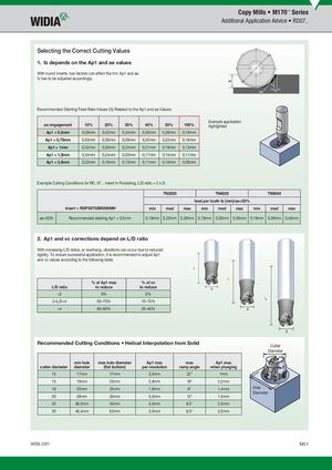
Selecting the Correct Cutting Values
1. fz depends on the Ap1 and ae values
With round inserts, two factors can affect the hm: Ap1 and ae. fz has to be adjusted accordingly.
Recommended Starting Feed Rate Values (fz) Related to the Ap1 and ae Values:
| ae engagement | 10% | 20% | 30% | 40% | 50% | 100% |
| Ap1 = 0,5mm | 0,59mm | 0,42mm | 0,34mm | 0,30mm | 0,26mm | 0,19mm |
| Ap1 = 0,75mm | 0,50mm | 0,36mm | 0,29mm | 0,25mm | 0,22mm | 0,16mm |
| Ap1 = 1mm | 0,42mm | 0,30mm | 0,24mm | 0,21mm | 0,19mm | 0,13mm |
| Ap1 = 1,5mm | 0,34mm | 0,24mm | 0,20mm | 0,17mm | 0,15mm | 0,11mm |
| Ap1 = 3,5mm | 0,22mm | 0,16mm | 0,13mm | 0,11mm | 0,10mm | 0,08mm |
Example application
Example Cutting Conditions for RD..07... Insert in Pocketing, L/D ratio = 2 x D:
TN2505 TN6525 TN6540
| TN2505 | TN6525 | TN6540 | ||||||||
| f | eed per to | oth fz (mm | )/ae>50% | |||||||
| insert = RDPX0702M0SNMH | min | med | max | min | med | max | min | med | max | |
| ae>50% | Recommended starting Ap1 = 0,5mm | 0,19mm | 0,22mm | 0,30mm | 0,19mm | 0,30mm | 0,35mm | 0,19mm | 0,30mm | 0,40mm |
2. Ap1 and vc corrections depend on L/D ratio
With increasing L/D ratios, or overhang, vibrations can occur due to reduced rigidity. To ensure successful application, it is recommended to adjust Ap1 and vc values according to the following table:
% of Ap1 max % of vc
L/D ratio to reduce to reduce
L
L
D
| L/D ratio | % of Ap1 max to reduce | % of vc to reduce |
| 0% | 0% | |
| 2 | 65–75% | 10–15% |
| >4 | 80–95% | 20–40% |
L
Recommended Cutting Conditions • Helical Interpolation from Solid
min hole max hole diameter Ap1 max max Ap1 max
cutter diameter diameter (fl at bottom) per revolution ramp angle when plunging
12 17mm 17mm 3,5mm 22° 1mm
D
Cutter Diameter
| cutter diameter | min hole diameter | max hole diameter (fl at bottom) | Ap1 max per revolution | max ramp angle | Ap1 max whenplunging |
| 12 | 17mm | 17mm | 3,5mm | 22° | 1mm |
| 15 | 18mm | 23mm | 2,8mm | 18° | 2,2mm |
| 16 | 20mm | 25mm | 1,9mm | 9° | 1,4mm |
| 20 | 28mm | 33mm | 3,5mm | 12° | 1,5mm |
| 25 | 36,5mm | 43mm | 3,5mm | 8.5° | 2,5mm |
| 30 | 46,4mm | 53mm | 3,5mm | 6.5° | 2,5mm |
Diameter
WID_Master16_IndexableMIlling_CopyMills_M050_M051_Metric_REBRAND.indd 51 L V i WID M 16 I d bl MIlli C Mill M050 M051 M i REBRANDD b 22015302PM12/2/15 3:02 PM