Общий каталог Widia 2017 - страница 698
Навигация
 Каталог Widia токарный инструмент 2017
 Каталог Widia трохоидальное фрезерование
 Каталог Widia техническое руководство по разверткам
 Каталог Widia фрезы со сменными пластинами 2016
 Каталог Widia достижения 2020
- Table of Contents
- Turning
- Turning • ISO Inserts
- Turning • Tools for External Turning and Internal Boring
- Turning • Tools for External Turning and Internal Boring
- Turning • Tools for Small Hole Boring
- com E1Turning • Grooving and Cut-Off
- Turning • Threading
- Indexable Milling
- Indexable Milling • Face Mills
- Indexable Milling • Chamfer Mills
- Indexable Milling • 90° Shoulder Mills
- Indexable Milling • Helical Mills
- Indexable Milling • Slotting Mills
- Indexable Milling • Copy Mills
- Solid End Milling
- Solid End Milling • High-Performance Solid Carbide End Mills
- Solid End Milling • General Purpose Solid Carbide End Mills
- Solid End Milling • High-Performance High-Speed Steel (HSS-E/PM)
- Solid End Milling • Burs
- Holemaking
- Holemaking • High-Performance Solid Carbide Drills
- Holemaking • Modular Drills
- Holemaking • Indexable Drills
- Holemaking • Modular Drills
- Holemaking • Indexable Drills
- Holemaking • Hole Finishing
- Tapping
- Tapping Portfolio
- Index by Order Number
- Index by Catalogue Number
- Global Contacts
- Informational Icons Guide
- Material Overview • DIN
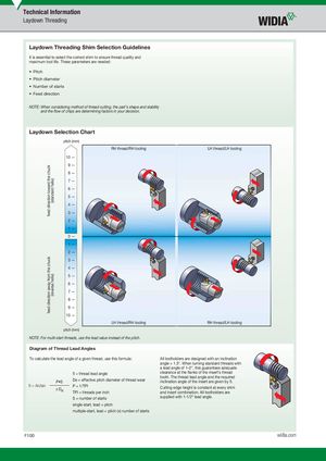
Laydown Threading Shim Selection Guidelines
It is essential to select the correct shim to ensure thread quality and maximum tool life. These parameters are needed:
- Pitch
- Pitch diameter
- Number of starts
- Feed direction
NOTE: When considering method of thread cutting, the part’s shape and stability and the fl ow of chips are determining factors in your decision.
Laydown Selection Chart
pitch (mm)
RH thread/RH tooling LH thread/LH tooling
10 — 9 — 8 — 7 —
6 — 5 — 4 — 3 — 2 — 1 — 0 — 1 — 2 — 3 — 4 — 5 — 6 — 7 — 8 — 9 — 10 —
| RH thread/LH tooling LH thread/RH tooling | ||
| pitch (mm) | ||
| NOTE: For multi-start threads, use the lead value instead of the pitch. | ||
| Diagram of Thread Lead Angles | ||
| To calculate the lead angle of a given thread, use this formula: | All toolholders are designed with an inclination | |
| angle = 1.5°. When turning standard threads with | ||
| a lead angle of 1–2°, this guarantees adequate | ||
| ß = thread lead angle | clearance at the fl anks of the insert’s thread | |
| tooth. The thread lead angle and the required | ||
| De = effective pitch diameter of thread wear | inclination angle of the insert are given by ß. |
P•S ß = Arctan P = 1/TPI / De Cutting edge height is constant at every shim TPI = threads per inch and insert combination. All toolholders are
supplied with 1-1/2° lead angle. S = number of starts single-start, lead = pitch multiple-start, lead = pitch (x) number of starts