Общий каталог Widia 2017 - страница 596
Навигация
 Каталог Widia токарный инструмент 2017
 Каталог Widia трохоидальное фрезерование
 Каталог Widia техническое руководство по разверткам
 Каталог Widia фрезы со сменными пластинами 2016
 Каталог Widia достижения 2020
- Table of Contents
- Turning
- Turning • ISO Inserts
- Turning • Tools for External Turning and Internal Boring
- Turning • Tools for External Turning and Internal Boring
- Turning • Tools for Small Hole Boring
- com E1Turning • Grooving and Cut-Off
- Turning • Threading
- Indexable Milling
- Indexable Milling • Face Mills
- Indexable Milling • Chamfer Mills
- Indexable Milling • 90° Shoulder Mills
- Indexable Milling • Helical Mills
- Indexable Milling • Slotting Mills
- Indexable Milling • Copy Mills
- Solid End Milling
- Solid End Milling • High-Performance Solid Carbide End Mills
- Solid End Milling • General Purpose Solid Carbide End Mills
- Solid End Milling • High-Performance High-Speed Steel (HSS-E/PM)
- Solid End Milling • Burs
- Holemaking
- Holemaking • High-Performance Solid Carbide Drills
- Holemaking • Modular Drills
- Holemaking • Indexable Drills
- Holemaking • Modular Drills
- Holemaking • Indexable Drills
- Holemaking • Hole Finishing
- Tapping
- Tapping Portfolio
- Index by Order Number
- Index by Catalogue Number
- Global Contacts
- Informational Icons Guide
- Material Overview • DIN
Technical Recommendations Separator Cut-Off System
(continued)
Eliminate chatter:
- Minimise tool blade and holder overhang.
- Minimise part overhang.
- Use strongest toolholder system.
- Use a more narrow width of insert.
- Chipbreaker might be too aggressive. (Call Technical Support.)
- Adjust speed and feed rate up or down.
- Hold workpiece rigidly.
- With a longer part, support with steady rest or live centre.
- Avoid machine dwell.
- Use S2 or X2 to reduce cutting forces.
Reduce cut-off nib on solid bar
or I.D. bur on tubing:
- Check tool height. Insert cutting edge should be on centre to 0,05mm above centreline of workpiece.
- To reduce nib on part, use a high lead angle-type insert. Lead angle on a cut-off insert reduces the nib, which remains on the workpiece. CAUTION: the higher the lead, the more tool-side defl ection.
- Use the narrowest possible cut-off insert to minimise the cut-off bur length.
- Reduce feed rate at the end of a cut.
- On most tubing-type parts, a 4° or 5° lead angle will be suffi cient.
- Add support to a long slender-type part.
- Maintain proper sub-spindle alignment.
- If nib or bur persists, call Technical Support about reducing hone size.
- Use small- or no-corner radius.
Eliminate built-up edge:
- Select proper grade for insert.
- Increase speed (RPM).
- Increase the feed rate.
- Use ample amounts of well-directed coolant (see Figure A on page E131).
Chamfer and cut-off operations:
- Use Separator S2 or X2.
- Groove or breakdown workpiece surface being machined.
- Machine the chamfer.
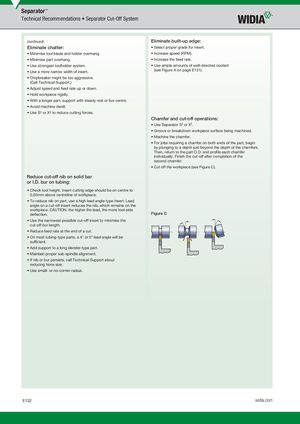
- For jobs requiring a chamfer on both ends of the part, begin by plunging to a depth just beyond the depth of the chamfers. Then, return to the part O.D. and profi le each chamfer individually. Finish the cut-off after completion of the second chamfer.
- Cut off the workpiece (see Figure C).
Figure C