Общий каталог Widia 2017 - страница 550
Навигация
 Каталог Widia токарный инструмент 2017
 Каталог Widia трохоидальное фрезерование
 Каталог Widia техническое руководство по разверткам
 Каталог Widia фрезы со сменными пластинами 2016
 Каталог Widia достижения 2020
- Table of Contents
- Turning
- Turning • ISO Inserts
- Turning • Tools for External Turning and Internal Boring
- Turning • Tools for External Turning and Internal Boring
- Turning • Tools for Small Hole Boring
- com E1Turning • Grooving and Cut-Off
- Turning • Threading
- Indexable Milling
- Indexable Milling • Face Mills
- Indexable Milling • Chamfer Mills
- Indexable Milling • 90° Shoulder Mills
- Indexable Milling • Helical Mills
- Indexable Milling • Slotting Mills
- Indexable Milling • Copy Mills
- Solid End Milling
- Solid End Milling • High-Performance Solid Carbide End Mills
- Solid End Milling • General Purpose Solid Carbide End Mills
- Solid End Milling • High-Performance High-Speed Steel (HSS-E/PM)
- Solid End Milling • Burs
- Holemaking
- Holemaking • High-Performance Solid Carbide Drills
- Holemaking • Modular Drills
- Holemaking • Indexable Drills
- Holemaking • Modular Drills
- Holemaking • Indexable Drills
- Holemaking • Hole Finishing
- Tapping
- Tapping Portfolio
- Index by Order Number
- Index by Catalogue Number
- Global Contacts
- Informational Icons Guide
- Material Overview • DIN
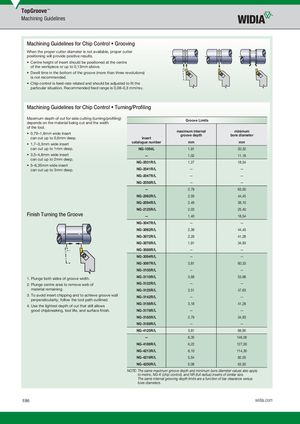
Machining Guidelines for Chip Control Grooving
When the proper cutter diameter is not available, proper cutter positioning will provide positive results.
- Centre height of insert should be positioned at the centre of the workpiece or up to 0,13mm above.
- Dwell time in the bottom of the groove (more than three revolutions) is not recommended.
- Chip control is feed-rate related and should be adjusted to fi t the particular situation. Recommended feed range is 0,08–0,3 mm/rev.
Machining Guidelines for Chip Control Turning/Profi ling
| p ggpig depends on the material being cut and the width of the tool. | Groove Limits | ||
| • 0,79–1,6mm wide insert can cut up to 0,6mm deep. | insert | maximum internal groove depth | minimum bore diameter |
| • 1,7–3,3mm wide insert | catalogue number | mm | mm |
| can cut up to 1mm deep. | NG-1094L | 1,91 | 20,32 |
| • 3,5–4,8mm wide insert 2 | — | 1,02 | 11,18 |
| can cut up to mm deep. • 5–635mm wide insert | NG-2031R/L | 1,27 | 18,54 |
| , can cut up to 3mm deep. | NG-2041R/L | — | — |
| NG-2047R/L | — | — | |
| NG-2058R/L | — | — | |
| — | 2,79 | 63,50 | |
| NG-2062R/L | 2,59 | 44,45 | |
| NG-2094R/L | 2,49 | 38,10 | |
| NG-2125R/L | 2,03 | 25,40 | |
| Finish Turning the Groove | — | 1,40 | 18,54 |
| NG-3047R/L | — | — | |
| NG-3062R/L | 2,39 | 44,45 | |
| NG-3072R/L | 2,29 | 41,28 | |
| NG-3078R/L | 1,91 | 34,93 | |
| NG-3088R/L | — | — | |
| NG-3094R/L | — | — | |
| NG-3097R/L | 3,81 | 60,33 | |
| NG-3105R/L | — | — | |
| 1. Plunge both sides of groove width. | NG-3110R/L | 3,68 | 53,98 |
| 2. Plunge centre area to remove web of | NG-3122R/L | — | — |
| material remaining. | NG-3125R/L | 3,51 | 47,63 |
| 3. To avoid insert chipping and to achieve groove wall perpendicularity, follow the tool path outlined. | NG-3142R/L | — | — |
| 4 Use the lihtest deth of cut that still allows | NG-3156R/L | 3,18 | 41,28 |
| . g p good chipbreaking, tool life, and surface fi nish. | NG-3178R/L | — | — |
| NG-3185R/L | 2,79 | 34,93 | |
| NG-3189R/L | — | — | |
| NG-4125R/L | 3,81 | 69,85 | |
| — | 6,35 | 146,05 | |
| NG-4189R/L | 6,22 | 127,00 | |
| NG-4213R/L | 6,10 | 114,30 | |
| NG-4219R/L | 5,54 | 82,55 | |
| NG-4250R/L | 5,08 | 63,50 |