Общий каталог Widia 2017 - страница 510
Навигация
 Каталог Widia токарный инструмент 2017
 Каталог Widia трохоидальное фрезерование
 Каталог Widia техническое руководство по разверткам
 Каталог Widia фрезы со сменными пластинами 2016
 Каталог Widia достижения 2020
- Table of Contents
- Turning
- Turning • ISO Inserts
- Turning • Tools for External Turning and Internal Boring
- Turning • Tools for External Turning and Internal Boring
- Turning • Tools for Small Hole Boring
- com E1Turning • Grooving and Cut-Off
- Turning • Threading
- Indexable Milling
- Indexable Milling • Face Mills
- Indexable Milling • Chamfer Mills
- Indexable Milling • 90° Shoulder Mills
- Indexable Milling • Helical Mills
- Indexable Milling • Slotting Mills
- Indexable Milling • Copy Mills
- Solid End Milling
- Solid End Milling • High-Performance Solid Carbide End Mills
- Solid End Milling • General Purpose Solid Carbide End Mills
- Solid End Milling • High-Performance High-Speed Steel (HSS-E/PM)
- Solid End Milling • Burs
- Holemaking
- Holemaking • High-Performance Solid Carbide Drills
- Holemaking • Modular Drills
- Holemaking • Indexable Drills
- Holemaking • Modular Drills
- Holemaking • Indexable Drills
- Holemaking • Hole Finishing
- Tapping
- Tapping Portfolio
- Index by Order Number
- Index by Catalogue Number
- Global Contacts
- Informational Icons Guide
- Material Overview • DIN
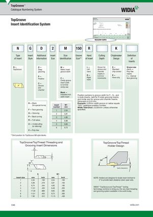
TopGroove
Insert Identifi cation System
NGD2M150RK
| N | G | D 2 | M 150 | R | K | ||||
| Type | Insert | Additional | Insert | Size Groove | Hand | Cutting | Chipbreaker | Defi nition | |
| of Insert | Style | Information | Size | Identifi cation | Size** | of Insert | Depth | Design | of |
| Inserts | |||||||||
| N — | D — | M — | L — | Shown for | K — | Groove size | |||
| TopGroove | Deep | Metric insert | Left | groove and | Standard | J or L — | |||
| grooving | groove width | hand | chamfer | chip control | Poly-Vee | ||||
| inserts in | inserts | ||||||||
| R — | 0,01mm | E — | I — Internal | ||||||
| P — | |||||||||
| Right | increments. | Hone only | face grooving |
Positive C — hand Circlip groove C — insert width
is nominal Groove circlip size and chamfer Blank — Indicates inch Position pertains to groove width for F-, G-, and width insert U-style inserts, radii for R-style grooving inserts, and circlip size for groove and chamfer inserts. Dimension in 0,01mm. B — Blank Example: 3,25mm width groove or radius equals
| (for special forms) insert | W1 | “325” catalogue position number. | |
| number | mm | Width Tolerance: ±0,025mm unless otherwise | |
| F — Face grooving | specifi ed. | ||
| 1 | 2,54 | ||
| G — Grooving | 2 | 3,81 | |
| P — Back turning | 3 | 4,95 | |
| R — Full radius | 4 | 6,98 | |
| U — Undercutting | 5 | 9,65 |
(or relieving) 6 9,73 V — Poly-Vee **Omit position for TopGroove NB-style blanks.
TopGroove/TopThread Threading and TopGroove/TopThread
Grooving Insert Dimensions Holder Design
back clearance
S W1
| insert size | mm | inch | mm | Inch | NOTE: Holders are designed to locate insert inclined to |
| 1 | 2,54 | .100 | 2,54 | .100 | 3° to provide back clearance down open side. |
| 2 | 5,56 | .219 | 3,81 | .150 | |
| 3 | 8,74 | .344 | 4,95 | .195 | |
| WIDIA™ TopGroove and TopThread™ tooling | |||||
| 4 | 11,51 | .453 | 6,48 | .255 | |
| technology combine to bring you the very best threading | |||||
| 5 | 17,48 | .688 | 9,65 | .380 | and grooving system available in the world today. |
| 6 | 11,51 | .453 | 9,73 | .383 | |
| 8 | 7,93 | .312 | 11,13 | .438 |
LWID_Master16_Turning_Grooving&CutOff_E046_E047_Metric_REBRAND.indd 46ViWID M16 TiGi&C Off E046 E047 M i REBRANDD b 9 20159 18AM 12/9/15 9:18 AM