Общий каталог Widia 2017 - страница 1682
Навигация
 Каталог Widia токарный инструмент 2017
 Каталог Widia трохоидальное фрезерование
 Каталог Widia техническое руководство по разверткам
 Каталог Widia фрезы со сменными пластинами 2016
 Каталог Widia достижения 2020
- Table of Contents
- Turning
- Turning • ISO Inserts
- Turning • Tools for External Turning and Internal Boring
- Turning • Tools for External Turning and Internal Boring
- Turning • Tools for Small Hole Boring
- com E1Turning • Grooving and Cut-Off
- Turning • Threading
- Indexable Milling
- Indexable Milling • Face Mills
- Indexable Milling • Chamfer Mills
- Indexable Milling • 90° Shoulder Mills
- Indexable Milling • Helical Mills
- Indexable Milling • Slotting Mills
- Indexable Milling • Copy Mills
- Solid End Milling
- Solid End Milling • High-Performance Solid Carbide End Mills
- Solid End Milling • General Purpose Solid Carbide End Mills
- Solid End Milling • High-Performance High-Speed Steel (HSS-E/PM)
- Solid End Milling • Burs
- Holemaking
- Holemaking • High-Performance Solid Carbide Drills
- Holemaking • Modular Drills
- Holemaking • Indexable Drills
- Holemaking • Modular Drills
- Holemaking • Indexable Drills
- Holemaking • Hole Finishing
- Tapping
- Tapping Portfolio
- Index by Order Number
- Index by Catalogue Number
- Global Contacts
- Informational Icons Guide
- Material Overview • DIN
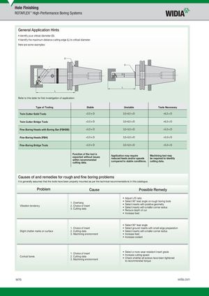
General Application Hints
- Identify your critical diameter (D).
- Identify the maximum distance cutting edge (L) to critical diameter.
Here are some examples:
D
D
D
L L
Refer to this table for fi rst investigation of application:
| Type of Tooling Stable | Unstable | Tests Necessary | |
| Twin Cutter Solid Tools | <3,5 x D | 3,5–6,5 x D | >6,5 x D |
| Twin Cutter Bridge Tools | <3,5 x D | 3,5–6,5 x D | >6,5 x D |
| Fine-Boring Heads with Boring Bar (FBHBB) | <3,5 x D | 3,5–5,0 x D | >5,0 x D |
| Fine-Boring Heads (FBH) | <3,5 x D | 3,5–5,0 x D | >5,0 x D |
| Fine-Boring Bridge Tools | <3,5 x D | 3,5–5,0 x D | >5,0 x D |
Function of the tool is Application may require Machining test may expected without issues reduced feeds and/or speeds be required to identify within recommended compared to stable conditions. cutting data. cutting data.
Causes of and remedies for rough and fi ne boring problems
It is generally assumed that the tools have been properly mounted as per the technical recommendations in this catalogue.
Problem Cause Possible Remedy
- Adjust L/D ratio
- Select 90° lead angle on rough boring tools
1. Overhang
- Select inserts with positive geometry
Vibration tendency 2. Choice of insert
- Select inserts with smaller corner radius
3. Cutting data
- Reduce depth of cut
- Increase feed
- Select 90° lead angle
1. Choice of insert Select ground inserts with small edge preparation
Slight chatter marks on surface 2. Cutting data Select inserts with smaller corner radius
3. Machining environment Increase feed
- Increase coolant
1. Choice of insert Conical bores 2. Cutting data 3. Machining environment
- Select a more wear-resistant insert grade
- Increase cutting speed
- Check whether all screws have been tightened to recommended torque