Каталог Widia инструментальная оснастка - страница 1056
Навигация
 Каталог Widia достижения 2021
 Брошюра Widia решения для аэрокосмической промышленности
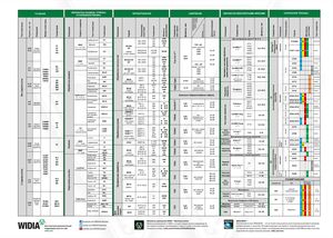 Брошюра Widia техническое руководство
 Каталог Widia токарный инструмент 2020
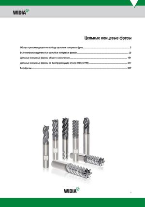 Каталог Widia цельные концевые фрезы
 Каталог Widia техническое руководство по разверткам
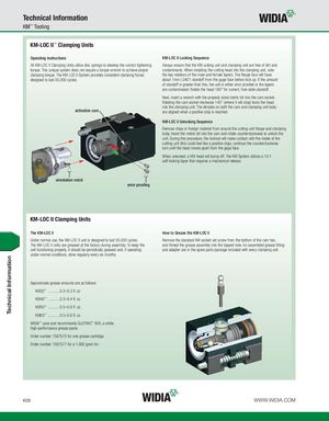
Technical Information KM™ Tooling KM-LOC II™ Clamping Units Operating Instructions KM-LOC II Locking Sequence All KM-LOC II Clamping Units utilize disc springs to develop the correct tightening Always ensure that the KM cutting unit and clamping unit are free of dirt and torque. This unique system does not require a torque wrench to achieve proper contaminants. When installing the cutting head into the clamping unit, note clamping torque. The KM LOC II System provides consistent clamping forces the key relations of the male and female tapers. The flange face will have designed to last 50,000 cycles. about 1mm (.040") standoff from the gage face before lock up. If the amount of standoff is greater than this, the unit is either error proofed or the tapers are contaminated. Rotate the head 180° for correct, free-state standoff. Next, insert a wrench with the properly sized metric bit into the cam socket. Rotating the cam socket clockwise 145° (where it will stop) locks the head into the clamping unit. The dimples on both the cam and clamping unit body activation cam are aligned when a positive stop is reached. KM-LOC II Unlocking Sequence Remove chips or foreign material from around the cutting unit flange and clamping body. Insert the metric bit into the cam and rotate counterclockwise to unlock the unit. During this procedure, the lockrod will make contact with the inside of the cutting unit (this could feel like a positive stop), continue the counterclockwise turn until the head moves apart from the gage face. When unlocked, a KM head will bump off. The KM System utilizes a 10:1 self-locking taper that requires a mechanical release. orientation notch error proofing KM-LOC II Clamping Units The KM-LOC II How to Grease the KM-LOC II Under normal use, the KM-LOC II unit is designed to last 50,000 cycles. Remove the standard M4 socket-set screw from the bottom of the cam hex, The KM-LOC II units are greased at the factory during assembly. To keep the and thread the grease assembly into the tapped hole. An assembled grease fitting unit functioning properly, it should be periodically greased and, if operating and adapter are in the spare parts package included with every clamping unit. under normal conditions, done regularly every six months. Approximate grease amounts are as follows: KM32™ ............0.2–0.3 fl. oz KM40™ ............0.3–0.4 fl. oz. KM50™ ............0.5–0.6 fl .oz. KM63™ ............0.5–0.6 fl. oz. WIDIA™ uses and recommends GLEITMO™ 805, a white, high-performance grease paste. Order number 1567575 for one grease cartridge. Order number 1567577 for a 1,000 gram tin. K20 WWW.WIDIA.COM Technical Information