Каталог Widia инструментальная оснастка - страница 1057
Навигация
 Каталог Widia достижения 2021
 Брошюра Widia решения для аэрокосмической промышленности
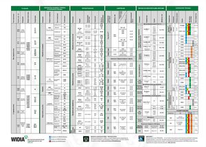 Брошюра Widia техническое руководство
 Каталог Widia токарный инструмент 2020
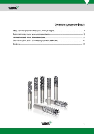 Каталог Widia цельные концевые фрезы
 Каталог Widia техническое руководство по разверткам
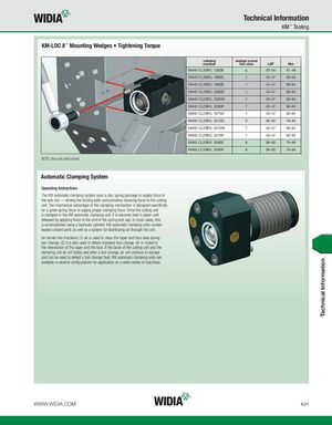
Technical Information KM™ Tooling KM-LOC II™ Mounting Wedges • Tightening Torque catalog wedge screw number hex size LBF Nm KM40 CL2SR/L 1260B 6 30–34 41–46 KM40 CL2SR/L 1660C 7 43–47 58–64 KM40 CL2SR/L 1660D 7 43–47 58–64 KM40 CL2SR/L 2060D 7 43–47 58–64 KM40 CL2SR/L 2560M 7 43–47 58–64 KM40 CL2SR/L 3260P 7 43–47 58–64 KM50 CL2SR/L 1675D 7 43–47 58–64 KM50 CL2SR/L 2075D 8 58–62 79–84 KM50 CL2SR/L 2575M 7 43–47 58–64 KM50 CL2SR/L 2575P 7 43–47 58–64 KM63 CL2SR/L 2090E 8 58–62 79–84 KM63 CL2SR/L 3290P 8 58–62 79–84 NOTE: Use a six-point socket. Automatic Clamping System Operating Instructions The KM automatic clamping system uses a disc spring package to supply force to the lock rod — driving the locking balls and providing clamping force to the cutting unit. The mechanical advantage of the clamping mechanism is designed specifically for a given spring force to supply proper clamping force. Once the cutting unit is clamped in the KM automatic clamping unit, it is securely held in place until released by applying force to the end of the spring end cap. In most cases, this is accomplished using a hydraulic cylinder. KM automatic clamping units contain sealed coolant ports as well as a system for distributing air through the unit. Air serves two functions: (1) air is used to clean the taper and face area during tool change; (2) it is also used to detect improper tool change. Air is routed to the intersection of the taper and the face. If the faces of the cutting unit and the clamping unit do not totally seal after a tool change, air will continue to escape and can be used to detect a tool change fault. KM automatic clamping units are available in several configurations for application on a wide variety of machines. WWW.WIDIA.COM K21 Technical Information