Каталог Widia инструментальная оснастка - страница 1055
Навигация
 Каталог Widia достижения 2021
 Брошюра Widia решения для аэрокосмической промышленности
 Брошюра Widia техническое руководство
 Каталог Widia токарный инструмент 2020
 Каталог Widia цельные концевые фрезы
 Каталог Widia техническое руководство по разверткам
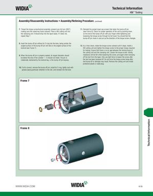
Technical Information KM™ Tooling Assembly/Disassembly Instructions • Assembly/Retiming Procedure (continued) 7. Thread the torque screw/lockrod assembly outward one full turn (360°), 11. Reinstall the socket-head cap screws that retain the bump-off pin making sure the raised key faces outward. Place a KM cutting unit into (see Frame 8). Check for proper operation of the unit by pushing down the clamping unit. It should drop into the taper easily. If it does not, on the end of the bump-off pin with your finger while tightening and repeat Step 7. loosening the torque screw through its full travel. You should feel the bump-off pin move in and out as the direction of the torque screw changes. 8. Insert the bump-off pin without its O-ring into the bore, being certain the angled surface of the bump-off pin will ride on the angled surface of the 12. As a final check, rotate the torque screw outward until it stops. Install a lockrod (see Frame 7). KM cutting unit and tighten the torque screw to the proper torque required for locking. Ensure that there is no air gap between the locking faces of the cutting unit and the clamping unit. Loosen the torque screw. Initially, 9. When the bump-off pin is properly seated, its largest diameter should resistance will be felt while loosening the screw, and again when bumping be below the end of the canister — it should not rotate. The pin is off the tool from the taper. Only use light force to loosen the screw after rotationally restrained by the lockrod key, in the bump-off pin keyway. the tool has been bumped off. Do not force the torque screw loose after tool bump-off or damage may result. Remove the cutting unit and install protective plastic or steel plug. 10. If all is correct, remove the bump-off pin, install its O-ring, lightly coat with grease paying particular attention to the slot, and reinstall into the bore. Frame 7 Frame 8 WWW.WIDIA.COM K19 Technical Information