Каталог Widia инструментальная оснастка - страница 1054
Навигация
 Каталог Widia достижения 2021
 Брошюра Widia решения для аэрокосмической промышленности
 Брошюра Widia техническое руководство
 Каталог Widia токарный инструмент 2020
 Каталог Widia цельные концевые фрезы
 Каталог Widia техническое руководство по разверткам
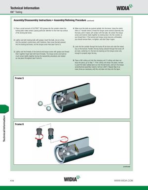
Technical Information KM™ Tooling Assembly/Disassembly Instructions • Assembly/Retiming Procedure (continued) 1. Place a small amount of GLEITMO™ 805 grease into the canister where the 4. Make sure the balls are pushed radially into the bores. Using the metric locking balls make contact, paying particular attention to the inner top surface Allen or T-handle wrench, thread the torque screw lockrod assembly into of the locking ball bores. the body until it makes soft contact with the balls. Be certain the torque screw and lockrod rotate together by looking down into the canister as you thread them. If the lockrod and torque screw become unthreaded, 2. Lightly coat both locking balls with grease. Insert the balls, one at a time, you should remove them, re-tighten, and start Step 4 again. into the canister’s central bore until it bottoms, then move the ball outward into the locking ball bores, not the torque screw hole (see Frame 5). 5. Look into the canister through the bump-off pin bore and note the raised key on the lockrod. Position the key facing outward through the bump-off 3. Lightly coat the threads of the lockrod and torque screw with grease and thread pin bore, centering it in the bore by backing out the torque screw only them together finger tight (left-hand threads). The torque screw and lockrod enough to properly align the key. must remain tightly together during the reassembly procedure and rotated as one piece throughout (see Frame 6). 6. Place a KM cutting unit into the clamping unit. If cutting unit does not drop into place, go to Step 7. If the cutting unit drops into place, remove it, push the balls radially back out into the ball bores, and turn the torque screw/lockrod assembly inward a full turn (360°). Repeat Step 6 as many times as necessary until the unit does not drop into the taper. Frame 5 Frame 6 (continued) K18 WWW.WIDIA.COM Technical Information