Каталог Widia инструментальная оснастка - страница 1052
Навигация
 Каталог Widia достижения 2021
 Брошюра Widia решения для аэрокосмической промышленности
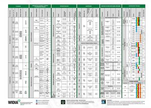 Брошюра Widia техническое руководство
 Каталог Widia токарный инструмент 2020
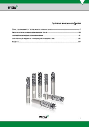 Каталог Widia цельные концевые фрезы
 Каталог Widia техническое руководство по разверткам
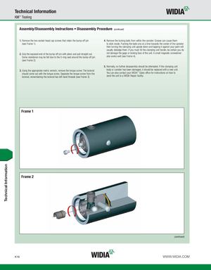
Technical Information KM™ Tooling Assembly/Disassembly Instructions • Disassembly Procedure (continued) 1. Remove the two socket-head cap screws that retain the bump-off pin 4. Remove the locking balls from within the canister. Grease can cause them (see Frame 1). to stick inside. Pushing the balls one at a time towards the center of the canister then turning the clamping unit upside down and tapping it against your palm will usually dislodge them. If you must hit the clamping unit harder, be certain you do 2. Grip the exposed end of the bump-off pin with pliers and pull straight out. not damage the gage or locking face of the unit. A small magnetic screwdriver Some resistance may be felt due to the O-ring seal around the bump-off pin also works well (see Frame 4). (see Frame 2). 5. Normally, no further disassembly should be attempted. If the clamping unit 3. Using the appropriate metric wrench, remove the torque screw. The lockrod body or canister has been damaged, it should be replaced with a new unit. should come out with the torque screw. Separate the torque screw from the You can also contact your WIDIA™ Sales office for instructions on how to lockrod, remembering the lockrod has left-hand threads (see Frame 3). send the unit to a WIDIA Repair facility. Frame 1 Frame 2 (continued) K16 WWW.WIDIA.COM Technical Information