Каталог Widia инструментальная оснастка - страница 1051
Навигация
 Каталог Widia достижения 2021
 Брошюра Widia решения для аэрокосмической промышленности
 Брошюра Widia техническое руководство
 Каталог Widia токарный инструмент 2020
 Каталог Widia цельные концевые фрезы
 Каталог Widia техническое руководство по разверткам
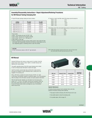
Technical Information KM™ Tooling Assembly/Disassembly Instructions • Repair Adjustment/Retiming Procedures for KM Manual Tooling Clamping Unit • Proper KM repair package catalog and order numbers: • T-wrench or metric-hex Allen wrench fits torque screw hex head for: KM32™ units.............................5mm KM40™ units.............................6mm catalog 3S order 3L ordernumbernumbernumberKM50™ units.............................10mm KM32-PKG 3S or 3L 1023697 1023698 KM63™ units.............................12mm KM80™ units.............................14mm KM40-PKG 3S or 3L 1023699 1023700 KM50-PKG 3S or 3L 1023726 1023725 • Hex Allen wrench fits small socket head screws to hold bump-off pin in place for: KM63-PKG 3S or 3L 1013701 1013702 KM32 units.............................2mmKM40 units.............................2,5mm KM80-PKG 3S or 3L. 1144980 1023701 KM50 units.............................3mm • Pair of pliers. KM63 units.............................5mm • WIDIA™ recommends and uses GLEITMO™ 805. KM80 units.............................5mm • Order number 1567575 for one grease cartridge. • Order number 1567577 for a 1,000 gram tin. • Clean towels or shop rags. • Solvent or degreaser that does not leave residue (used to clean inside the taper and canister upon disassembly). Should the unit become contaminated, you can use a degreasing agent or something similar to clean the surfaces. CAUTION DO NOT USE silicone cleaner or WD-40™-type lubricants. NOTE: All KM repair packages include the bump-off pin, lock rod, torque screw, two chrome balls, two socket head cap screws, and O-ring. KM Manual Standard KM Manual units require a torque wrench to activate. Using the proper torque wrench value is critical. Tighter is not better because over tightening can cause damage. The specific operating torque of the KM manual clamping units is listed on each unit (torque value information is listed to the right). The KM connection must be kept clean and free from nicks and burrs. KM plugs are available to ensure cleanliness when a cutting unit is not engaged in the clamping unit. activation KM size torque (ft. lbs.) torque (Nm) drive size When a KM head is unlocked, the head will bump-off. KM’s 10:1 taper KM32™ 7–9 10–12 5mm is self-locking, and therefore, requires a mechanical release. This is accomplished within the design of the KM System and does not require operator intervention. KM40™ 9–12 12–16 6mm After the head has been released, you will need to turn the torque screw KM50™ 20–25 27–34 10mm another 3/4–1-1/2 turns. This rotation will feel free of resistance. When the free turning motion stops, the head can be pulled from the clamping unit. KM63™ 35–40 47–54 12mm Do not turn the lock screw further, as damage can occur to the lockrod KM80™ 58–63 79–85 14mm and/or bump-off pin. Operator Maintenance All tooling showing damage must be replaced. Burrs and nicks should be removed by stoning and/or polishing. • Use plugs to protect clamping units when they are not in use. • Use spindle wipers to clean the clamping units. • For spindle wipers, refer to page J31. (continued) WWW.WIDIA.COM K15 Technical Information