Каталог Widia инструментальная оснастка - страница 1050
Навигация
 Каталог Widia достижения 2021
 Брошюра Widia решения для аэрокосмической промышленности
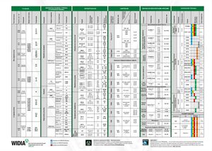 Брошюра Widia техническое руководство
 Каталог Widia токарный инструмент 2020
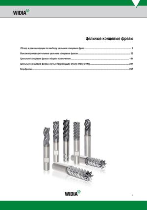 Каталог Widia цельные концевые фрезы
 Каталог Widia техническое руководство по разверткам
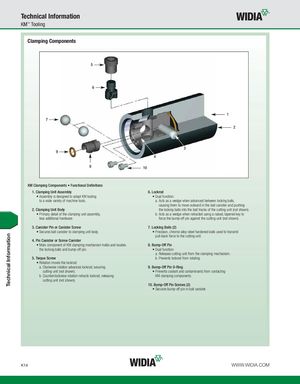
Technical Information KM™ Tooling Clamping Components 5 6 1 7 2 3 9 4 8 10 KM Clamping Components • Functional Definitions 1. Clamping Unit Assembly 6. Lockrod • Assembly is designed to adapt KM tooling • Dual function: to a wide variety of machine tools. a. Acts as a wedge when advanced between locking balls, causing them to move outward in the ball canister and pushing 2. Clamping Unit Body the locking balls into the ball tracks of the cutting unit (not shown). • Primary detail of the clamping unit assembly, b. Acts as a wedge when retracted using a raised, tapered key to less additional hardware. force the bump-off pin against the cutting unit (not shown). 3. Canister Pin or Canister Screw 7. Locking Balls (2) • Secures ball canister to clamping unit body. • Precision, chrome alloy-steel hardened balls used to transmit pull-back force to the cutting unit. 4. Pin Canister or Screw Canister • Main component of KM clamping mechanism holds and locates 8. Bump-Off Pin the locking balls and bump-off pin. • Dual function: a. Releases cutting unit from the clamping mechanism. 5. Torque Screw b. Prevents lockrod from rotating. • Rotation moves the lockrod: a. Clockwise rotation advances lockrod, securing 9. Bump-Off Pin O-Ring cutting unit (not shown). • Prevents coolant and contaminants from contacting b. Counterclockwise rotation retracts lockrod, releasing KM clamping components. cutting unit (not shown). 10. Bump-Off Pin Screws (2) • Secures bump-off pin in ball canister. K14 WWW.WIDIA.COM Technical Information