Каталог Widia инструментальная оснастка - страница 1049
Навигация
 Каталог Widia достижения 2021
 Брошюра Widia решения для аэрокосмической промышленности
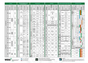 Брошюра Widia техническое руководство
 Каталог Widia токарный инструмент 2020
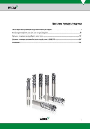 Каталог Widia цельные концевые фрезы
 Каталог Widia техническое руководство по разверткам
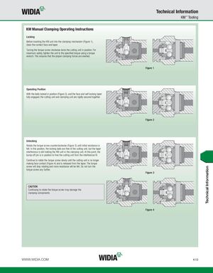
Technical Information KM™ Tooling KM Manual Clamping Operating Instructions Locking Before inserting the KM unit into the clamping mechanism (Figure 1), clean the contact face and taper. Turning the torque screw clockwise locks the cutting unit in position. For maximum safety, tighten the unit to the specified torque using a torque wrench. This ensures that the proper clamping forces are exerted. Figure 1 Operating Position With the balls locked in position (Figure 2), and the face and self-locking taper fully engaged, the cutting unit and clamping unit are rigidly secured together. Figure 2 Unlocking Rotate the torque screw counterclockwise (Figure 3) until initial resistance is felt. In this position, the locking balls are free of the cutting unit, but the taper interference is still holding the KM unit in the clamping unit. At this point, the bump-off pin is in position to free the cutting unit from the interference fit. Continue to rotate the torque screw slowly until the cutting unit is no longer making face contact (Figure 4) and is released from the taper. The torque screw will stop rotating and more resistance will be felt. Do not turn the torque screw any further. Figure 3 CAUTION Continuing to rotate the torque screw may damage the clamping components. Figure 4 WWW.WIDIA.COM K13 Technical Information