Каталог Widia достижения 2020 - страница 160
Навигация
 Каталог Widia инструмент для обработки отверстий 2017
 Каталог Widia токарный инструмент 2020
 Каталог Widia монолитный инструмент 2017
 Каталог Widia техническое руководство по разверткам
 Каталог Widia инструментальная оснастка
- Table of contents
- All-Star
- Indexable Milling
- VSM890™-12
- VXF™
- VXF-07
- VXF-09
- VXF-12
- VXF-16
- VXF Best practices
- Heavy Metal Extensions
- Solid ER Collets
- VSM
- VSM11
- VSM17
- Solid End Milling
- The VariMill Family
- 70NS
- 4U50 & 4U80
- 4U50
- 4U80
- 49N9
- D503
- General Purpose End Mills
- Holemaking
- TDMX
- Top Cut 4
- Turning
- WGC
- WK15CT
- Railway Tooling
- Bar Peeling
- Informational Icons Guide
- Customer Application Support (CAS)
- Material Overview • DIN
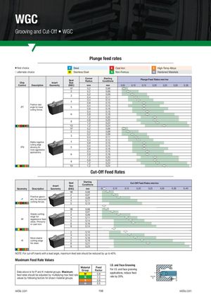
Grooving and Cut-Off • WGC
Plunge feed rates
| first choice | P | Steel | K | Cast Iron | S | High-Temp Alloys |
| v | ||||||
| alternate choice | M | Stainless Steel | N | Non-Ferrous | H | Hardened Materials |
| j |
| Corner | Starting | Plunge Feed Rates mm/rev | |
| Seat | Radius | Conditions |
Chip Insert Size
| Geometry Description Control (SSC) | mm | 0,35 0,30 0,25 0,20 0,15 0,10 0,05 mm |
| 1F | 0,2 | 0,06 |
| 2 | 0,2 | 0,08 |
| 0,2 | 0,09 | |
| 3 | ||
| 0,4 | 0,11 | |
| 0,4 | 0,12 | |
| 4 | ||
| 0,8 | 0,15 | |
| Positive rake | 0,4 | 0,15 |
| angle for lower -PT 5 | ||
| 0,8 | 0,16 | |
| cutting forces. | ||
| 0,4 | 0,15 | |
| 6 | 0,8 | 0,18 |
| 1,2 | 0,20 | |
| 0,8 | 0,20 | |
| 8 | ||
| 1,2 | 0,22 | |
| 10 | 1,2 | 0,24 |
| 1F | 0,2 | 0,06 |
| 2 | 0,2 | 0,08 |
0,2 0,09 3 0,4 0,11 0,4 0,12
Stable negative 4 0,8 0,15
cutting edge 0,4 0,15
| -PN | allowing for | 5 | ||
| 0,8 | 0,16 | |||
| more aggressive |
| applications. | 0,4 | 0,15 |
| 6 | 0,8 | 0,18 |
| 1,2 | 0,20 | |
| 0,8 | 0,20 | |
| 8 | ||
| 1,2 | 0,22 | |
| 10 | 1,2 | 0,24 |
| Cut-Off Feed Rates |
| Seat | Starting | Cut-Off Feed Rates mm/rev | |
| Insert | Size | Conditions |
| Geometry Description | Geometry (SSC) | 0,40 0,35 0,30 0,25 0,20 0,15 0,10 0,05 mm |
| 1B | 0,06 | |
| 2 | 0,07 | |
| Positive geom- | 3 | 0,09 |
| -F etry for reduced | ||
| 4 | 0,11 | |
| cutting forces. | ||
| 5 | 0,13 | |
| 1B | 0,06 | |
| 2 | 0,07 | |
| Stable cutting | 3 | 0,09 |
| edge for | 4 | 0,11 |
| -M aggressive feed | ||
| 5 | 0,14 | |
| rates. Primarily | ||
| in cast iron. | 6 | 0,16 |
| 8 | 0,14 | |
| 2 | 0,10 | |
| 3 | 0,14 | |
| Most stable | 4 | 0,16 |
| -R cutting edge | 5 | 0,19 |
| for steel. | 6 | 0,21 |
8 0,23 NOTE: For cut-off inserts with a lead angle, maximum feed rate should be reduced by up to 40%. Maximum Feed Rate Values I.D. and Face Grooving
Material Feed
| Group | Factor | For I.D. and face grooving | |
| Data above is for P and K material groups. Maximum | applications, reduce feed | ||
| feed rates should be adjusted by multiplying max feed rate | M | 0.8 | |
| N | 1.2 | rate by 20%. |
values by following factors for shown material groups. S 0.8 H 0.5