Каталог Tungaloy инструмент для автоматов швейцарского типа - страница 309
Навигация
 Общий каталог Tungaloy 2020 - 2021
 Каталог Tungaloy глубокое сверление 2
 Каталог Tungaloy зубофрезерование
 Брошюра Tungaloy новая продукция
 Каталог Tungaloy глубокое сверление 1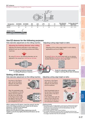
EZ sleeve 1
Eccentric sleeve for TungDrillTwisted LSC ℓ3 ℓ4
2
LPR Hole diameter Cutting edge height
| Designation | DCONWS | DCONMS | BD | LSC | LPR | ℓ3 | ℓ4 | adjustment | adjustment | ||
| EZ2025 | 20 | 25 | 46 | 49 | 5 | 32.5 | 4 | +0.4 ~ -0.2 | +0.2 ~ -0.15 | ||
| EZ2532 | 25 | 32 | 51 | 52 | 5 | 38 | 4 | +0.4 ~ -0.2 | +0.2 ~ -0.15 |
SPARE PARTS 3 Designation Wrench EZ... P-2.5
Use EZ sleeves for the following purposes
| Hole diameter adjustment on the milling machine | Adjusting cutting edge height on lathe | 4 | ||
| Adjusting the fi nishing diameter when milling | Lathe | |||
| Adjusting the fi nishing diameter in tool-rotating ap- | Adjusting of the cutting edge height in work rotating | |||
| plications such as on machining centres and milling | applications such as on lathes: | |||
| machines: |
By using EZ sleeve, the fi nishing diameter can be By using EZ sleeve, the cutting edge height can be adjusted 5
adjusted in the range from +0.6 mm to -0.2 mm. in the range from +0.3 mm to -0.2 mm. It results in eliminating troubles caused by improper cutting-edge height. 6 Scale for adjusting finishing diameter Scale for adjusting cutting edge
in milling (Periphery of sleeve) height in turning (Front face of sleeve)
Setting of EZ sleeve
Hole diameter adjustment on the milling machine Adjusting cutting edge height on lathe
| As shown in the Figure | Flat As shown in the Figure | 7 Fixing bolt “A” |
| right, set the EZ sleeve | right, set the EZ sleeve | Flat |
| between the drill shank | between the drill shank | Fixing bolt “B” |
| and the toolholder. | and the toolblock. | |
| EZ sleeve | ||
| EZ sleeve Flange | ||
| Flange | ||
| Align the graduated scale | Align the graduated scale on | X-axis of |
| machine | ||
| on the periphery of the EZ | the front face of the Esleeve | 8 |
| sleeve with the center of | with the center of the fl at of | (+) |
| Fixing bolt “A” | ||
| the fl at of the drill fl ange. | the drill fl ange. | |
| In the Figure shown right, | In the Figure shown right, the | |
| the sleeve is set so that | sleeve is set so that the cen- | |
| the fi nishing diameter will | ter of the drill will shift by 0.1 | |
| be increased by 0.4 mm. | Fixing bolt “B” mm to the plus (+) direction. | (-) |
| When rotating the EZ sleeve, insert the wrench into the | Cautious points |
| hole at the flange periphery and rotate the EZ sleeve. | 9 • The scale is only a rough guide, so be sure to measure the actual |
| Screws A + B have to be loosened. | drilling diameter to confi rm the result. Especially in turning, test |
| machining is recommended as the drilling diameter will vary | |
| Secure the drill by screw A. | according to theadjustment. |
| Secure the EZ sleeve by lightly tightening screw B. | • Can not be used for collect chuck holders. |
| Tighten screw B only lightly otherwise EZ sleeve can be | • For smaller adjustment, the drill itself will interfere with the hole |
| damaged! | diameter. It is recommended that hole diameter should be adjusted |
to a larger diameter than the drill diameter.