
A/E-SDUCR/L
S c re w - o n boring b a r s , for positive 5 5 ° rhombic inserts
| 93° | 30˚ | | | DMIN GAM | F GAMP | LH WF f2 | LF | | DCONMS | H | | |
| Cutting edge styleU | | | | | | | | | | | Righthan | d (R) shown. |
| Designation | Material | DMIN | DCONMS | WF | LF | LH H | f2 | GAMP | GAMF | RE | Insert | Torque |
| A10K-SDUCR/L07-D130 | Steel | 13 | 10 | 7 | 125 | 20 9 | 2 | 0 | -10 | 0.4 | DC0702... | 1.2 |
| A12M-SDUCR/L07-D160 | Steel | 16 | 12 | 9.3 | 150 | 24 11 | 3.3 | 0 | -6 | 0.4 | DC0702... | 1.2 |
| A16Q-SDUCR/L07-D200 | Steel | 20 | 16 | 11.3 | 180 | 32 15 | 3.3 | 0 | -5 | 0.4 | DC0702... | 1.2 |
| E10H-SDUCR07-D130 | Carbide | 13 | 10 | 7 | 100 | 25 9 | 1.9 | 5 | -3.5 | 0.4 | DC0702... | 1.2 |
| E10M-SDUCR/L07-D130 | Carbide | 13 | 10 | 7 | 150 | 25 9 | 2 | 0 | -10 | 0.4 | DC0702... | 1.2 |
| E12J-SDUCR07-D160 | Carbide | 16 | 12 | 9.3 | 110 | 27 11 | 3.2 | 0 | -6 | 0.4 | DC0702... | 1.2 |
| E12Q-SDUCR/L07-D160 | Carbide | 16 | 12 | 9.3 | 180 | 27 11 | 3.3 | 0 | -6 | 0.4 | DC0702... | 1.2 |
*Torque: Recommended clamping torque (N∙m) **RE: Standard corner radius When using a right or left hand insert, the right hand insert (R) is used for the left hand toolholders (SDUCL** type), and the left hand insert (L) is used for the right hand DPMTDPMT toolholders (SDUCR** type).
SPARE PARTS
DXGUDXGU
| | Designation | Clamping screw | Wrench |
| A1**-SDUCR/L07-D1*0 | | CSTB-2.5S | T-8F |
| EP**EP** | A16Q-SDUCR/L07-D200 | | CSTB-2.5 | T-8F |
| E1**-SDUCR/L07-D1*0 | | CSTB-2.5S | T-8F |
TC**TC** TP**TP** A/E-SDQCR/L VB**VB**
S c re w - o n boring b a r s , for positive 5 5 ° rhombic inserts
| VC**VC** | | | DMIN | H |
| 107.5° | | | |
| WB**WB* | | 15.5˚ | | |
| | GAMF | | LH | LF | |
| WXGUWXGU | | | GAMP | | | |
| Cutting edge style Q | | | | | |
| | | | | | Right hand (R) shown. |
| YW**YW** | | Designation | Material | DMIN DCONMS | | WF LF LH H | | | | f2 | GAMP GAMF RE** | | | Insert | Torque* |
| A10K-SDQCR/L07-D130 | | Steel | 13 | 10 | 7.6 | 125 | 20 | 9 | 2.6 | 0 | -8 | 0.4 | DC**0702... | 1.2 |
| A12M-SDQCR/L07-D160 | | Steel | 16 | 12 | 8.6 | 150 | 24 | 11 | 2.6 | 0 | -6 | 0.4 | DC**0702... | 1.2 |
| A16Q-SDQCR/L07-D200 | | Steel | 20 | 16 | 10.6 | 180 | 32 | 15 | 2.6 | 0 | -5 | 0.4 | DC**0702... | 1.2 |
| E10H-SDQCR07-D130 | | Carbide | 13 | 10 | 7.6 | 100 | 25 | 9 | 2.5 | 0 | -8 | 0.4 | DC**0702... | 1.2 |
| E10M-SDQCR/L07-D130 | | Carbide | 13 | 10 | 7.6 | 150 | 25 | 9 | 2.6 | 0 | -8 | 0.4 | DC**0702... | 1.2 |
| E12J-SDQCR07-D160 | | Carbide | 16 | 12 | 8.6 | 110 | 27 | 11 | 2.5 | 0 | -6 | 0.4 | DC**0702... | 1.2 |
| E12Q-SDQCR/L07-D160 | | Carbide | 16 | 12 | 8.6 | 180 | 27 | 11 | 2.6 | 0 | -6 | 0.4 | DC**0702... | 1.2 |
| *Torque: Recommended clamping torque (N∙m) **RE:Standard corner radius | | | | | | | | | | | | | | | |
| When using a right or left hand insert, the right hand insert (R) is used for the left hand toolholders (SDQCL** type), and the left hand insert (L) is used for the right hand | | | | | | | | | | | | | | | |
| toolholders (SDQCR** type). | | | | | | | | | | | | | | | |
| SPARE PARTS | | | | | | | | | | | | | | |
| | Designation Clamping screw | | Wrench | | | | | | | | | | | |
| A1**-SDQCR/L07-D**0 | CSTB-2.5S | | T-8F | | | | | | | | | | | |
| E1**-SDQCR/L07-D**0 | CSTB-2.5S | | T-8F | | | | | | | | | | | |
Reference pages: A/E-SDUCR/L, A/E-SDQCR/L: Insert → 2-15 -, CBN → 2-63 -, PCD → 2-70, Sleeve → 4-31
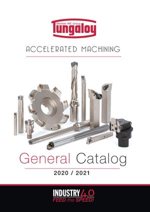 Общий каталог Tungaloy 2020 - 2021
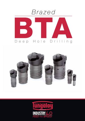 Каталог Tungaloy глубокое сверление 2
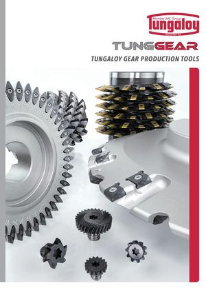 Каталог Tungaloy зубофрезерование
 Брошюра Tungaloy новая продукция
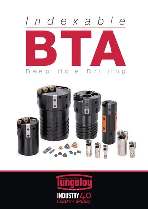 Каталог Tungaloy глубокое сверление 1