Брошюра Tungaloy новая продукция - страница 92
Навигация
 Каталог Tungaloy глубокое сверление 2
 Каталог Tungaloy глубокое сверление 1
 Каталог Tungaloy зубофрезерование
 Общий каталог Tungaloy 2020 - 2021
 Каталог Tungaloy инструмент для автоматов швейцарского типа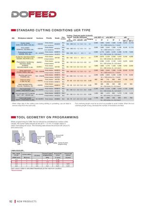
STANDARD CUT TING CONDITIONS UER T YPE
| Cutting Feedper tooth:fz | (mm/t) | |||||||||||||
| ISO | Workpiece material | Hardness | Priority | Grade | Chip- breaker | Vc (m/min) ø16 ~ ø22ø25 ~ ø50 speed Tool dia.: DCX(mm) | Plunging | ø16, CI n | CT= 2 Vf | ø18, C n | ICT= 2 Vf | n | ø20 CICT = 3 | Vf CICT = 4 |
| Carbon steels S45C,C45, S55C, C55, etc. | - 300HB | First choice Low resistance | AH3225 | MJ ML | 100 - 300 0.5 - 1.2 0.5 - 1.5 | 0.1 | 3,980 | 7,960 Vc = | 3,540 200 m/m | 7,080 in,fz = 1 | 3,180 mm/t | 9,540 | 12,720 | |
| Alloy steels SCM440, 42CrMo4, etc. | - 300HB | First choice Low resistance | AH3225 | MJ ML | 100 - 300 0.5 - 1.2 0.5 - 1.5 | 0.1 | 3,980 | 7,960 Vc = | 3,540 200 m/m | 7,080 in,fz = 1 | 3,180 mm/t | 9,540 | 12,720 | |
| Prehardened steels NAK80, PX5, etc. | 30 - 40HRC | First choice for impact resistance | AH8015 AH3225 | MJ MJ | 100 - 200 0.5 - 1 0.5 - 1 | 0.1 | 2,980 | 4,770 Vc =1 | 2,650 50 m/mi | 4,240 n,fz = 0. | 2,390 8 mm/t | 5,740 | 7,650 | |
| A | ustenitic stainless steels SUS304, X5CrNi18-9, etc. | - 200HB | First choice for impact resistance | AH130 | ML MJ | 80 - 150 0.3 - 1 0.3 - 1 | 0.1 | 2,390 | 2,870 Vc =1 | 2,120 20 m/mi | 2,550 n,fz = 0. | 1,910 6 mm/t | 3,440 | 4,590 |
| Precipitation hardening stainless steels | 28HRC - | First choice for impact resistance | AH130 | ML MJ | 80 - 150 0.3 - 0.8 0.3 - 0.8 | 0.1 | 2,390 | 2,390 Vc =1 | 2,120 20 m/mi | 2,120 n,fz = 0. | 1,910 5 mm/t | 2,870 | 3,820 | |
| SUS630, X5CrNiCuNb16-4,etc. | 40HRC - | First choice for impact resistance | AH130 | ML MJ | 80 - 120 0.3 - 0.5 0.3 - 0.5 | 0.1 | 1,990 | 1,600 Vc =1 | 1,770 00 m/mi | 1,420 n,fz = 0. | 1,590 4 mm/t | 1,910 | 2,550 | |
| Gray cast irons | 150 - 250HB | First choice | AH8015 | MJ | 100 - 30005 - 1205 - 15 | 01 | 3,980 | 7,960 | 3,540 | 7,080 | 3,180 | 9,540 | 12,720 | |
| FC250, GG25, 250, etc. | for impact resistance | AH3225 | MJ | . . . . | . | Vc = | 200 m/m | in,fz = 1 | mm/t | |||||
| Ductile cast irons FCD400, etc. | 150 - 250HB | First choice for impact resistance | AH8015 AH3225 | MJ MJ | 80 - 200 0.5 - 1.2 0.5 - 1.5 | 0.1 | 2,980 | 5,960 Vc = | 2,650 150 m/m | 5,300 in,fz = 1 | 2,390 mm/t | 7,170 | 9,560 | |
| Titanium alloy | - 40HRC | First choice | AH130 | MJ | 30 - 60 03 - 0803 - 08 | 008 | 800 | 960 | 710 | 860 | 640 | 1,160 | 1,540 | |
| Ti-6Al-4V, etc. | for wear resistance | AH8015 | MJ | . . . . | . | Vc = | 40 m/min | ,fz = 0.6 | mm/t | |||||
| Heat-resistant alloy Inconel, Hasteroy, etc. | - 40HRC | First choice for impact resistance | AH8015 | ML MJ | 20 - 50 0.2 - 0.5 0.2 - 0.5 | 0.05 | 600 | 360 Vc = | 530 30 m/min | 320 ,fz = 0.3 | 480 mm/t | 440 | 580 | |
| Hot mold steel SKD61, X40CrMoV5-1, etc. | 40~50HRC | First choice for impact resistance | AH8015 AH3225 | MJ MJ | 80 - 150 0.1 - 0.5 0.1 - 0.5 | 0.05 | 2,390 | 1,440 Vc =1 | 2,120 20 m/mi | 1,280 n,fz = 0. | 1,910 3 mm/t | 1,720 | 2,300 | |
| H | ot mold steel of D.T.C materials DAC, DH, DIEVER, etc. | 40~50HRC | First choice for impact resistance | AH8015 AH3225 | MJ MJ | 50 - 100 0.1 - 0.5 0.1 - 0.5 | 0.05 | 1,590 | 960 Vc = | 1,410 80 m/min | 850 ,fz = 0.3 | 1,270 mm/t | 1,150 | 1,530 |
| S | Cold mold steels KD11, X153CrMoV12, etc. | 50~60HRC | First choice | AH8005 | MJ | 50 - 70 0.1 - 0.3 0.1 - 0.3 | 0.03 | 1,190 | 480 Vc = | 1,060 60 m/min | 430 ,fz = 0.2 | 950 mm/t | 570 | 760 |
- When chips stay in the cutting zone during slotting or pocketing, use air blast to - Tool overhang length must be as short as possible to avoid chatter. When the tool remove chips from the work area overhang length is long, decrease the number of revolutions and feed
TOOL GEOMETRY ON PROGR AMMING
When programming for CAM, the tool should be considered as a radius cutter. Usually, the corner radius should be set as R = 1.5 mm. If a larger radius is used, overcutting will occur. The following table shows the amount left uncut (t1) and overcut (t2).
t2 Amount left Amount left overcut uncut RE t1 Max. depth of cut
LE RPG t1 RPG Corner R when
programming
LNMU0303UER...
| Max. depth | Corner R when | Amount left | Amount left | ||||
| of cut | Corner radius | ||||||
| LE (mm) | programming | uncut | overcut | ||||
| APMX (mm) | RE (mm) | RPG | t1 (mm) | t2 (mm) |
| 0.9 | 1 | 3.5 | 1 | 0.48 | - |
| 0.9 | 1 | 3.5 | 1.5 | 0.39 | - |
| 0.9 | 1 | 3.5 | 2 | 0.3 | 0.12 |
| 0.9 | 1 | 3.5 | 2.5 | 0.21 | 0.31 |
Each value in table is calculated theoretically at the maximum condition. *Recommended