Общий каталог Sumitomo 2019 - 2020 - страница 459
Навигация
 Каталог Sumitomo запасные части
 Каталог Sumitomo сплавы и режимы
 Техническая информация Sumitomo
 Каталог Sumitomo пластины с алмазными вставками Sumidia
 Каталог Sumitomo специальные торцевые фрезы
 Общий каталог Sumitomo 2018 - 2019
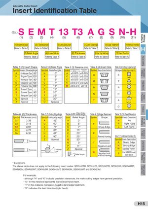
High-speedCast IronNon-ferrousMetalChamferingGroove /T-SlotR / 3DProfilingRadiusMulti-PurposeHigh FeedShoulderMillingFace MillingMillingCutters Indexable Cutter Insert Insert Identification Table (Ex.) S EMT 13 T3 A G S N-H (1) (2) (3) (4) (5) (6) (7) (8) (9) (10) (11) (1) Insert Shape (3) Tolerance (5) Cutting Edge Length (7) Cutting Edge Angle (9) Edge Treatment (11) Additional Information Refer to Table 1 Refer to Table 3 Refer to Table 5 Refer to Table 7 Refer to Table 9 Refer to Table 11 H (2) Relief Angle (4) Insert Hole (6) Thickness (8) Wiper Edge Relief Angle (10) Feed Direction Refer to Table 2 Refer to Table 4 Refer to Table 6 Refer to Table 8 Refer to Table 10 Table 1: (1) Insert Shape Table 2: (2) Relief Angle Table 3: (3) Tolerance (mm) Table 4: (4) Insert Hole Table 5: (5) Cutting Edge Length Symbol Insert Shape Angle Symbol Relief Angle Symbol Inscribed Circle(mm)Thickness(mm)Symbol Shape (Cross Section) Shape Cutting Edge Length (L) A Parallelogram Type 85° N 0° A ±0.025 ±0.025 W S H Trigon Type 120° A 3° C ±0.025 ±0.025 L L Rectangular Type 90° B 5° E ±0.025 ±0.025 O Octagonal Type 135° C 7° K ±0.05 to ±0.15 ±0.025 M T L P Pentagonal Type 108° P 11° M ±0.05 to ±0.15 ±0.13 R R R Round Type Q D 15° L S Square Type 90° E 20° N H T Triangular Type 60° F 25° L Q Special Q G 30°XSpecialQOSpecial T A L O L Table 6: (6) Thickness Table 7: (7) Cutting Edge Angle Table 8 (8) Wiper Edge Relief Angle Table 9: (9) Edge Treatment Table 10 (10) Feed Direction Symbol Thickness (mm) Symbol Cutting edge angle Symbol Relief Angle Symbol Shape Symbol Feed Direction 02 2.38 A 45° A 3° N No 03 3.18 D 60° B 5° F R Right Hand T3 3.97 E 75° C 7° Sharp Edge L Left Hand 04 4.76 F 85° D 15° 06 6.35 H 87° E 20° E P 90° F 25° Round Honing Table 11 (11) Additional Information (Ex.) Z Special G 30° Symbol Code Description Thickness N 0° T A Sharp Edge P 11° Negative Land H Strong Edge Thickness Cutting edge Z Special W Large Edge Treatment angle Relief Angle S Negative Land+ Round Honing S For WBMR InsertMain Blade * Exceptions The above table does not apply to the following insert codes: SPCH42TR, SPCH42R, SPCH53TR, SPCH53R, SDKN42MT, SDKN42M, SDKN53MT, SDKN53M, SEKN42MT, SEKN42M, SEKN53MT and SEKN53M. For example, · although "H" and "K" indicate precision tolerances, the main cutting edges have general precision. · "M" in this instance represents the Neutral Hand insert. · "T" in this instance represents negative land edge treatment. · "R" indicates the feed direction (right hand). H15